Connector and connector assembly
a technology of connectors and assemblies, applied in the direction of incorrect coupling prevention, coupling device connections, electrical devices, etc., can solve the problems of reducing the resilient force of the lock arm and the inability to reliably strengthen the lock arm, so as to reduce the height of the connector
- Summary
- Abstract
- Description
- Claims
- Application Information
AI Technical Summary
Benefits of technology
Problems solved by technology
Method used
Image
Examples
first embodiment
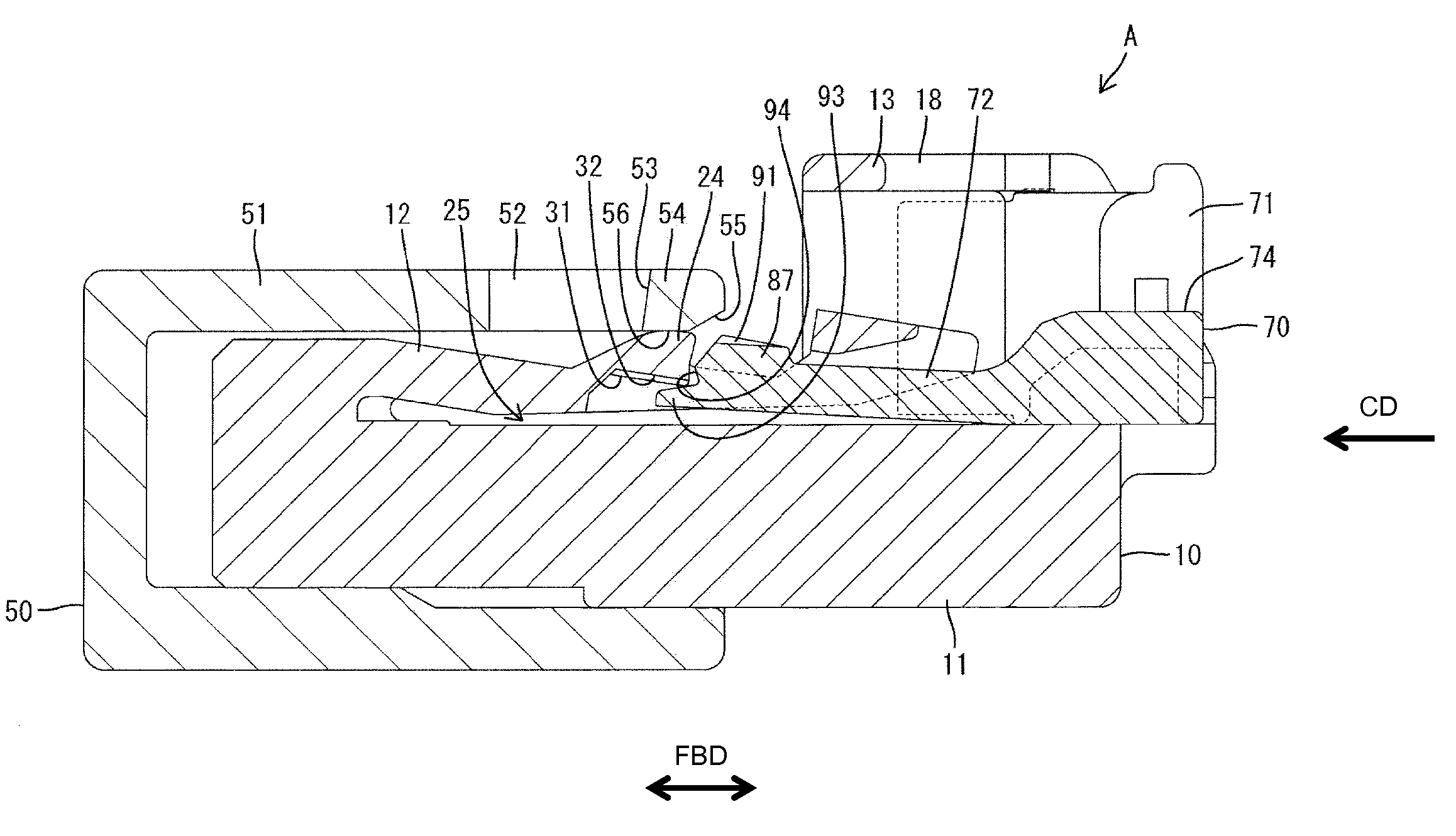
[0101]As shown in FIGS. 24 to 27, a substantially rectangular block-shaped protrusion 102 projects up near a front part of a resilient arm 101 of the detector 100. An auxiliary protrusion 103 having substantially the same shape as in the first embodiment projects up on the upper end surface of the protrusion 102. The auxiliary protrusion 103 is in the form of a rib extending in forward and backward directions FBD in a substantially widthwise central part of the upper or outer end surface of the protrusion 102. Thus, the auxiliary protrusion 103 is narrower than the protrusion 102.
[0102]A projecting distance of the auxiliary protrusion 103 along the deforming direction DD (the height direction HD) from the protrusion 102 is smaller than the projecting distance of the protrusion 102 from the resilient arm portion 101 along the deforming direction DD. Further, the upper surface of the auxiliary protrusion 103 is tapered to incline down or in toward the back. The auxiliary protrusion 10...
second embodiment
[0109]The narrow auxiliary protrusion 103 of the connector B of this second embodiment projects in the height direction on the protrusion 102 and a part of the inner surface of the accommodating recess 31 is recessed to form the auxiliary recess 32 for receiving the auxiliary protrusion 103 at the detection position DP. The steeply inclined surface 104 is formed at an area of the front surface of the protrusion 102 corresponding to the auxiliary protrusion 103 in the width direction WD and is inclined with respect to forward and backward directions FBD. The steeply inclined surface 104 is substantially continuous and flush with the front surface of the auxiliary protrusion 103. Further, the areas of the front surface of the protrusion 102 not corresponding to the auxiliary protrusion 103 in the width direction WD form the moderately inclined surfaces 105 and have a smaller angle of inclination with respect to forward and backward directions FBD than the steeply inclined surface 104....
third embodiment
[0114]A rear end part of the accommodating recess 35 of the third embodiment is cut obliquely to form at least one escaping portion 36 that is open in or down and back. The escaping portion 36 avoids interference of an auxiliary protrusion 103 with a rear end part of the lower surface of a lock projection 24 as the moderately inclined surfaces 105 slide in contact with an opening edge 31E. Therefore, a guide function by the sliding contact of the opening edge 31E and the moderately inclined surfaces 105 is displayed continuously until the insertion of the auxiliary protrusion 103 into the auxiliary recess 35 (insertion of a protrusion 102 into an accommodating recess 31) is complete.
[0115]The present invention is not limited to the above described and illustrated embodiment. For example, the following embodiments are also included in the technical scope of the present invention.
[0116]The detecting member may be configured to be incapable of restricting the resilient deformation of t...
PUM
 Abstract
Description
Claims
Application Information
 - R&D
- Intellectual Property
- Life Sciences
- Materials
- Tech Scout
- Unparalleled Data Quality
- Higher Quality Content
- 60% Fewer Hallucinations
Browse by: Latest US Patents, China's latest patents, Technical Efficacy Thesaurus, Application Domain, Technology Topic, Popular Technical Reports.
© 2025 PatSnap. All rights reserved.Legal|Privacy policy|Modern Slavery Act Transparency Statement|Sitemap|About US| Contact US: help@patsnap.com


