
Apparatus for Moving Railcars via Self-Propulsion

a technology for moving railcars and self-propulsion, which is applied in the direction of locomotive propulsion types, locomotive transmissions, locomotives, etc., can solve the problems of inconvenient and time-consuming attachment of railcars to traditional locomotives, ineffective solution of moving railcars by hand, and more space than is available in the railroad yard. achieve the effect of preventing unnecessary damage or the need for untimely maintenan

Inactive Publication Date: 2013-09-19
JOHNSON HYDRAMOTIVE
View PDF6 Cites 0 Cited by
  • Summary
  • Abstract
  • Description
  • Claims
  • Application Information

AI Technical Summary

Benefits of technology

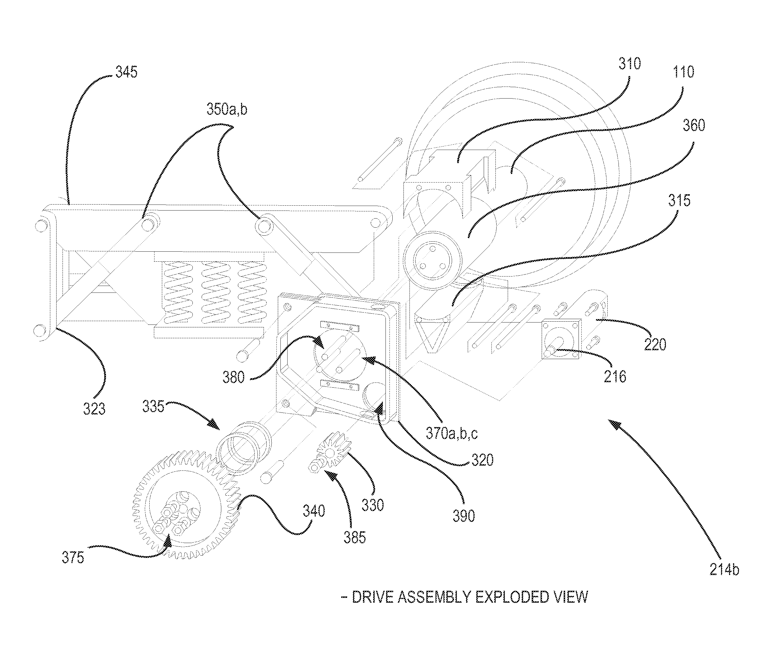
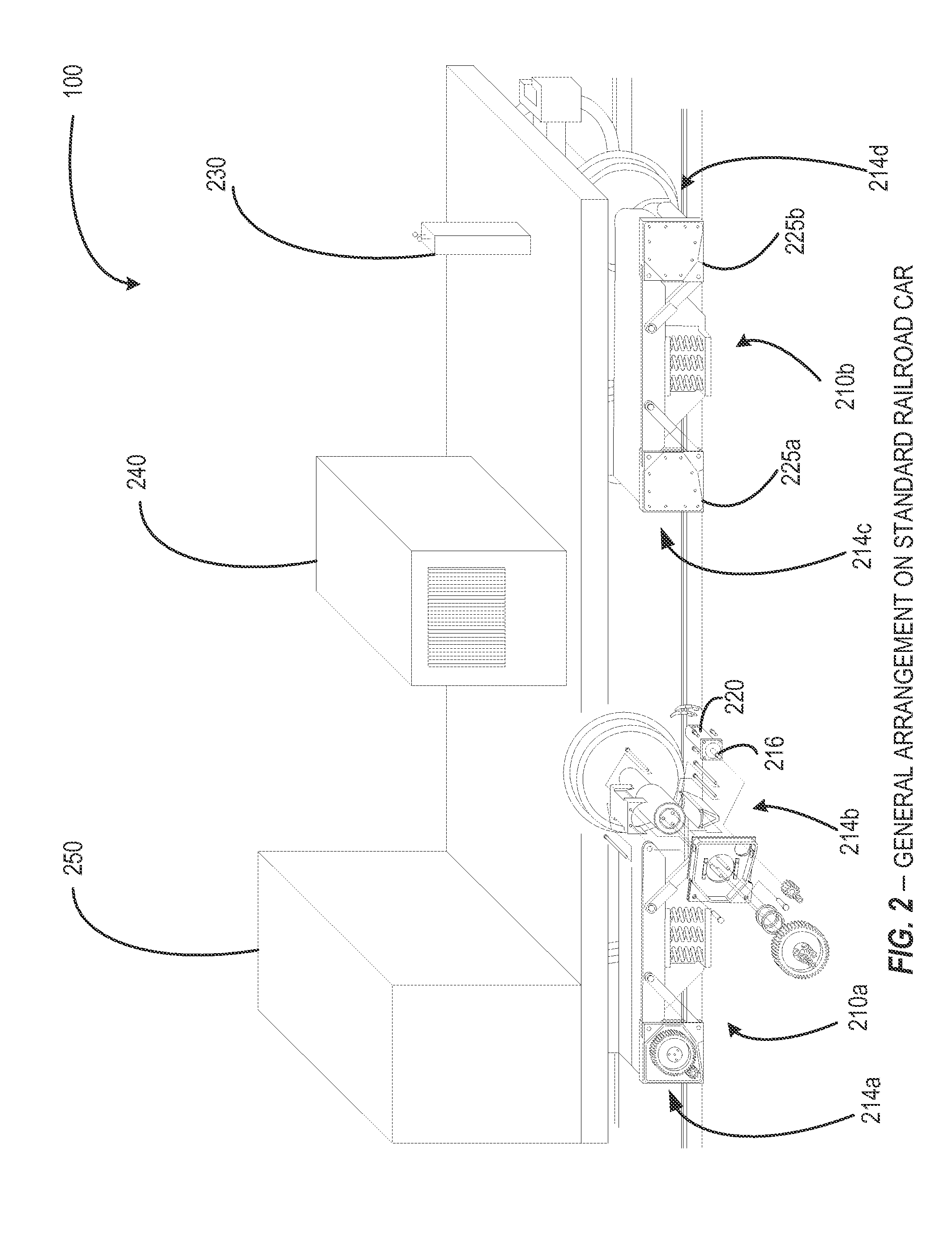
The present patent is about a way to turn a standard railcar into a self-propelling one that can move independently and act as a locomotive for other railcars. This is achieved by retrofitting a drive assembly to the railcar in a way that protects the hydraulic motor, hoses, and connectors from damage and debris on the tracks and prevents unnecessary maintenance. The technical effect of this invention is to provide a more reliable and durable self-propelling railcar that can safely and efficiently move other railcars.

Problems solved by technology

Attaching railcars to a traditional locomotive is both inconvenient and time-consuming, and it may require more space than is available in a railroad yard.
Additionally, moving a railcar by hand is not an effective solution as it requires substantial manpower and many man hours.
Therefore, for these applications, the method of attaching railcars to a traditional locomotive is likewise inconvenient and expensive.
This external means of pushing a railcar, however, is neither convenient nor efficient as an external means such as a traditional locomotive requires additional operational and maintenance costs.
Further, to effectively clear brush from the right of way, the railcar fitted with the brush clearing apparatus would need to make more than one pass, and an external means for moving the railway car, such as a locomotive, can not easily and effectively change direction as would be necessary in such a situation.
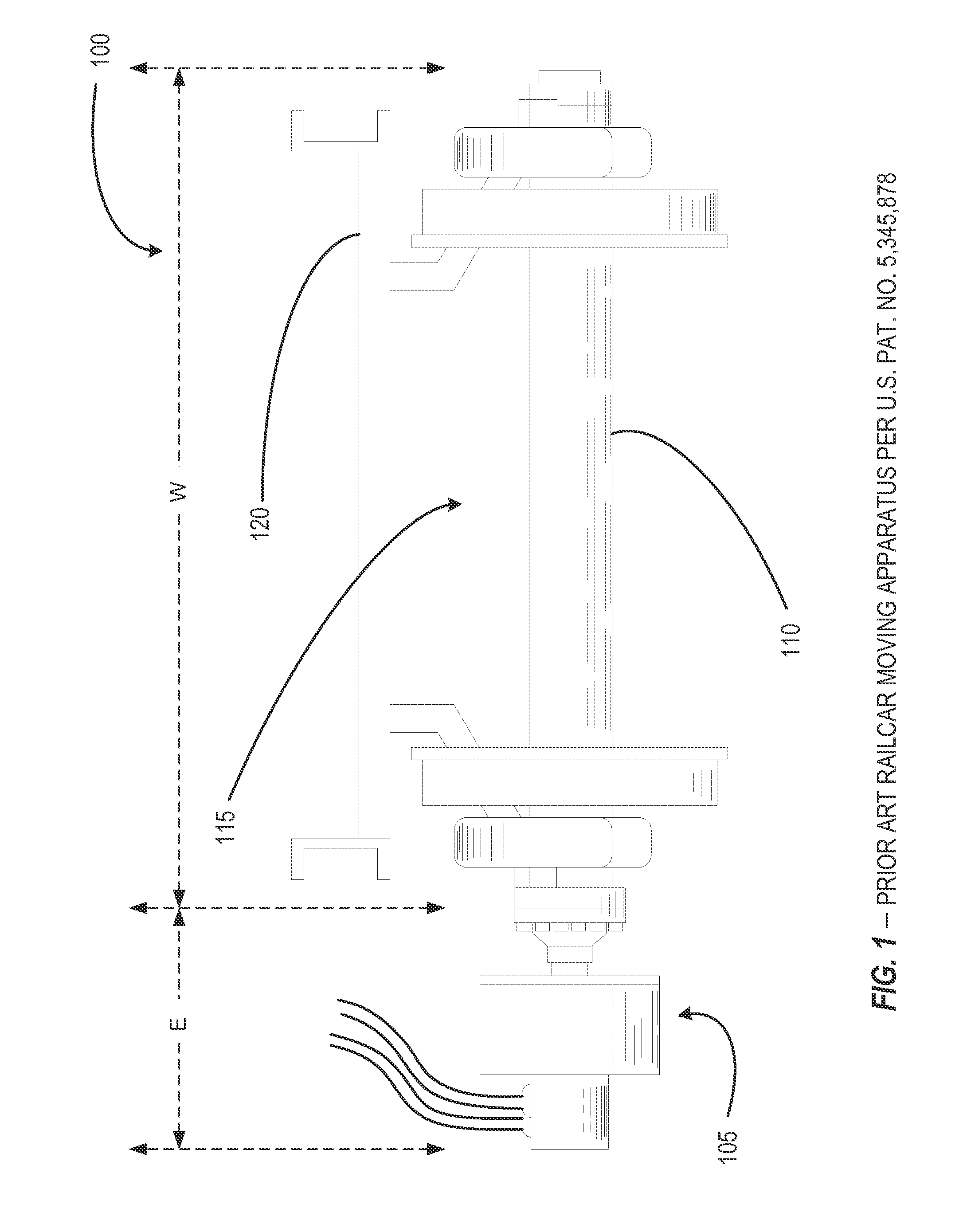
Such an arrangement exposes the hydraulic motors to trackside debris (e.g., plant and tree overgrowth, railroad equipment, signage, etc.) as well as other obstructions capable of damaging the motors.

Method used


Image

  • Apparatus for Moving Railcars via Self-Propulsion
  • Apparatus for Moving Railcars via Self-Propulsion
  • Apparatus for Moving Railcars via Self-Propulsion

Examples


Embodiment Construction

[0020]For the purpose of promoting an understanding of the principles of the present disclosure, reference will now be made to the embodiments illustrated in the drawings and specific language will be used to describe the same. It will, nevertheless, be understood that no limitation of the scope of the disclosure is thereby intended; any alterations and further modifications of the described or illustrated embodiments, and any further applications of the principles of the disclosure as illustrated therein, are contemplated as would normally occur to one skilled in the art to which the disclosure relates. All limitations of scope should be determined in accordance with and as expressed in the claims.

[0021]Briefly described, and according to one embodiment, aspects of the present disclosure generally relate to an apparatus for converting a standard railcar into a self-propelled railcar, such self-propelled railcar having the capacity to move independently and serve as a locomotive for...


PUM


Abstract

An apparatus that can be affixed to a standard railcar thereby converting a standard railcar into a self-propelled railcar, such self-propelled railcar having the capacity to move independently and serve as a locomotive for moving other railcars. The apparatus includes a railcar drive assembly that can be retrofitted to a railcar in such a manner that the hydraulic motor, hoses, and connectors of the drive assembly motor mechanism are positioned below the bed of the railway car and between the drive assembly housing and the railway car's wheel-and-truck assembly. This drive assembly design ensures that the drive assembly motor mechanism's hydraulic motor, hoses, and connectors are protected from general railway track debris as well as obstructions in the railroad right of way, and helps prevent unnecessary damage or the need for untimely maintenance.

Description

CROSS REFERENCE TO RELATED APPLICATION[0001]This application claims benefit under 35 U.S.C. §119(e) of U.S. Provisional Patent Application No. 61 / 611,264, filed Mar. 15, 2012, and entitled “Apparatus for Moving Railcars”, which is hereby incorporated by reference as if set forth herein in its entirety.TECHNICAL FIELD[0002]The present disclosure relates generally to an apparatus for converting a standard railcar into a self-propelled railcar. More particularly, the present disclosure relates to a mountable apparatus that can be affixed or retrofitted to a standard railcar that will provide the power necessary to propel the railcar, thereby converting the standard railcar into a self-propelled railcar having the capacity to move independently and serve as a locomotive for moving other railcars.BACKGROUND[0003]In various industrial situations there is a need for a convenient and economical means for moving railcars without attaching the railcars to a traditional locomotive, which then ...

Claims


Application Information

Patent Timeline
Patent Type & Authority Applications(United States)
IPC IPC(8): B61C7/00
CPCB61C9/00B61C7/00
Inventor JOHNSON, CHIPLEY H.
Owner JOHNSON HYDRAMOTIVE
Learn More