Phase change graded sma actuators

a technology of sma actuators and phase change, applied in the direction of valves, mechanical devices, engine components, etc., can solve the problem of relative rapid change between remembered shapes or lengths of sma actuators

Inactive Publication Date: 2013-09-19
GM GLOBAL TECH OPERATIONS LLC
View PDF8 Cites 31 Cited by
  • Summary
  • Abstract
  • Description
  • Claims
  • Application Information

AI Technical Summary

Problems solved by technology

This can lead to a relatively rapid change between remembered shapes or lengths of an SMA actuator, which is undesirable in many circumstances where a slower actuation is desired for aesthetic and / or functional reasons.

Method used


Image

  • Phase change graded sma actuators
  • Phase change graded sma actuators
  • Phase change graded sma actuators

Examples


Embodiment Construction

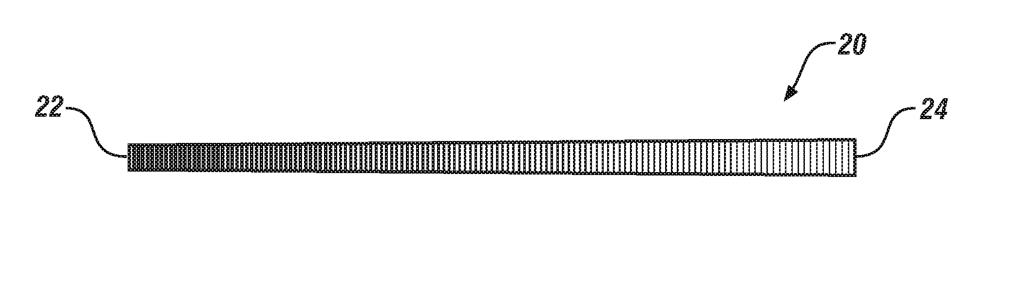
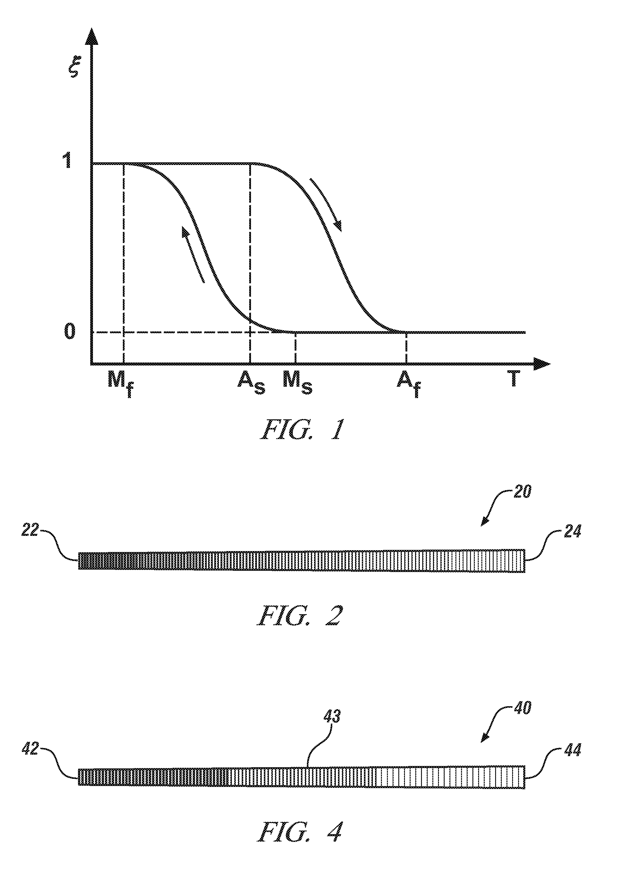
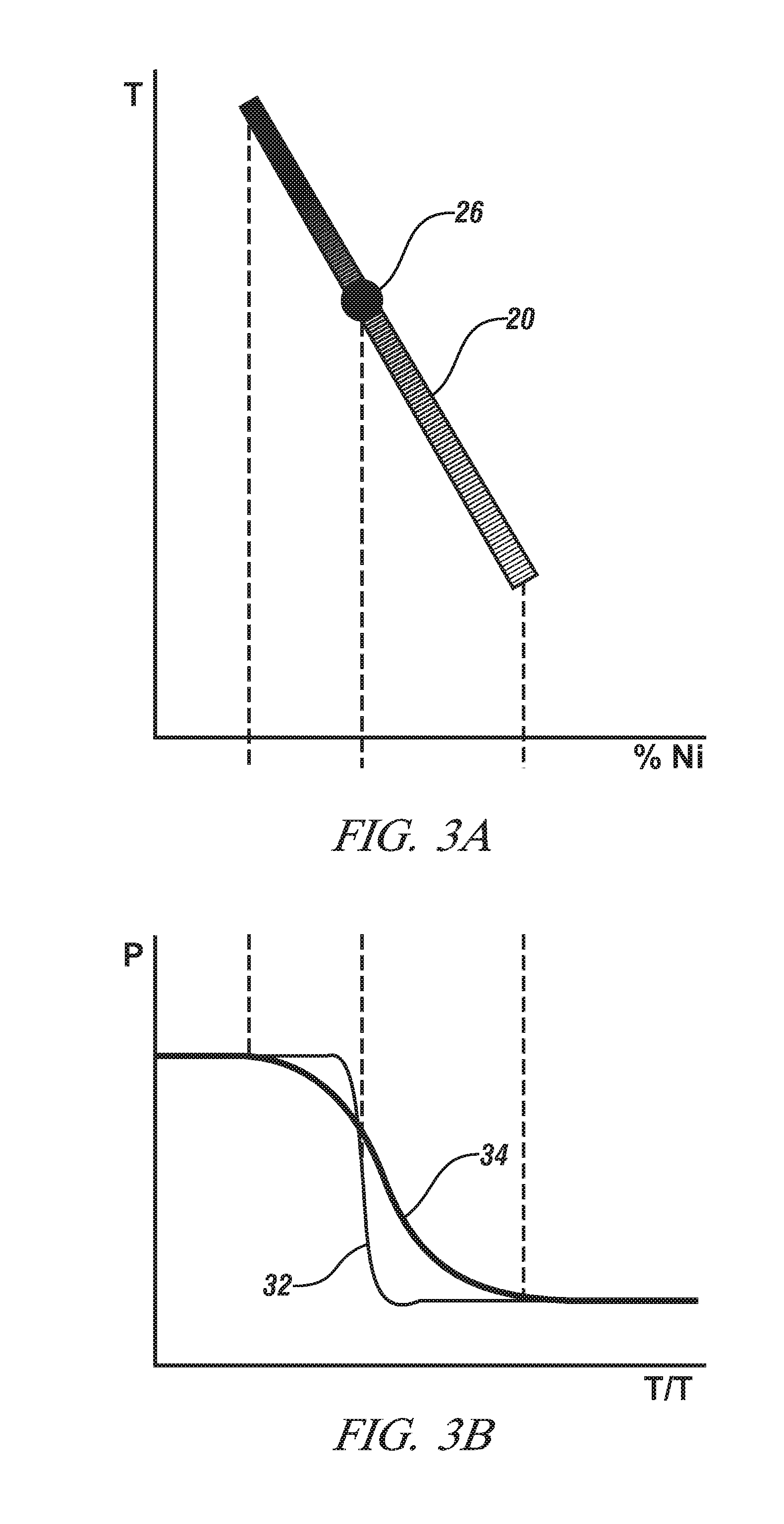
[0017]In accordance with an exemplary embodiment of the invention, a shape memory alloy element is configured to undergo a graded phase change, along a dimension of the shape memory alloy element in response to thermal stimulus. By graded phase change along a dimension of the SMA element, it is meant that at a point in time, the ratio of Austenitic phase to Martensitic phase of the SMA material is different at one position along this dimension than the ratio at a different position along the dimension. Since it is the conversion of the shape memory alloy from Austenitic phase to Martensitic phase and vice versa that induces the shape memory displacement response of the SMA element, then providing a gradation in the phase change response will provide a gradation in the shape memory displacement response, as further discussed below with respect to the Figures.

[0018]Suitable shape memory alloy materials for fabricating the conformable shape memory element(s) described herein include, b...


PUM

PropertyMeasurementUnit
crystal lattice structureaaaaaaaaaa
shape memory effectaaaaaaaaaa
shape memoryaaaaaaaaaa

Abstract

A shape memory alloy element is disclosed that is configured to undergo a graded phase change along a dimension of the shape memory alloy element in response to thermal stimulus. This graded phase change produces a graded displacement response of the shape memory element.

Description

FIELD OF THE INVENTION[0001]Exemplary embodiments of the invention are related to metallic shape memory alloy (“SMA”) actuators and, more specifically, to SMA actuators having unique thermal response characteristics.BACKGROUND[0002]Shape memory alloys are well-known in the art. Shape memory alloys are alloy compositions with at least two different temperature-dependent phases. The most commonly utilized of these phases are the so-called Martensite and Austenite phases. In the following discussion, the Martensite phase generally refers to the more deformable, lower temperature phase whereas the Austenite phase generally refers to the more rigid, higher temperature phase. When the shape memory alloy is in the Martensite phase and is heated, it begins to change into the Austenite phase. The temperature at which this phenomenon starts is often referred to as the Austenite start temperature (As). The temperature at which this phenomenon is complete is called the Austenite finish temperat...

Claims


Application Information

Patent Timeline
Patent Type & Authority Applications(United States)
IPC IPC(8): F16K31/00C21D8/00C22F1/00
CPCC21D8/00C22F1/00F16K31/002C22C19/03C21D2211/008C22F1/10C22F1/183C21D2201/01C21D2211/001C22F1/006
Inventor BROWNE, ALAN L.JOHNSON, NANCY L.SAROSI, PETER MAXWELL
Owner GM GLOBAL TECH OPERATIONS LLC
Why Eureka
Try Eureka