Apparatus and method for forming absorbent cores

a technology of absorbent cores and apparatuses, applied in the direction of lamination apparatus, lamination, chemical apparatus and processes, etc., can solve the problems of waste of material resources, complicated chip removal, and inability to adapt machine configurations

Active Publication Date: 2013-09-19
CURT G JOA
View PDF15 Cites 19 Cited by
  • Summary
  • Abstract
  • Description
  • Claims
  • Application Information

AI Technical Summary

Benefits of technology

[0043]Next, the cores can be discrete and unwrapped, discrete and wrapped, discrete and wrapped with the wrap longer than the core and glued to form a teabag type structure (in this embodiment the

Problems solved by technology

This complicates the removal of the chip because the severing might not create a continuous cut out chip, with possibly some strands of the web material still coupling the chip with the web.
Not all machine configurations can be adapted from a full length poly chassis to a poly insert configuration due to space and/or cost restrictions.
This is a waste of the material resource and adds additional cost to the product.
High levels of super absorbent material, however, tend to be more difficult to control and to maintain in position.
Thus, some fluff undesirably becomes entrained in the vacuum stream.
Machine processes have become more complex as speeds of machines have increased, so air handling systems

Method used


Image

  • Apparatus and method for forming absorbent cores
  • Apparatus and method for forming absorbent cores
  • Apparatus and method for forming absorbent cores

Examples


second embodiment

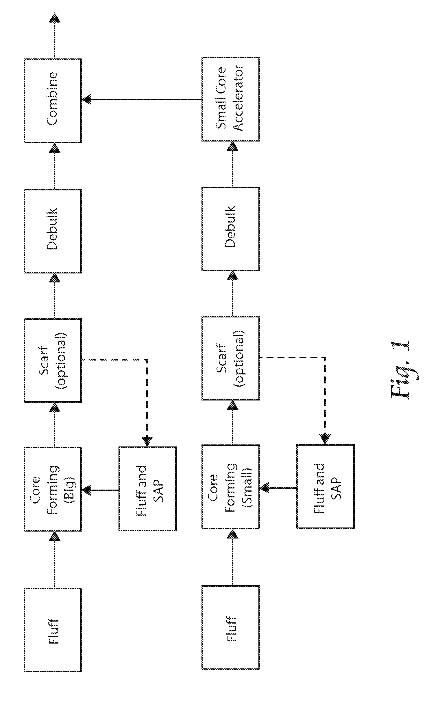
[0087]Referring now to FIG. 15, a schematic of the present invention is shown, a large and small continuous core, both formed on a web.

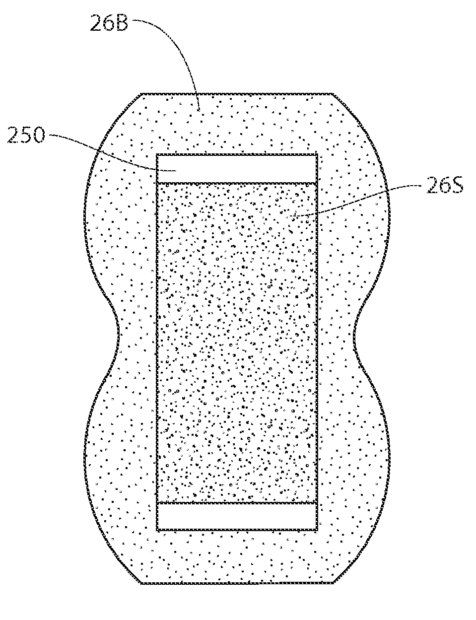
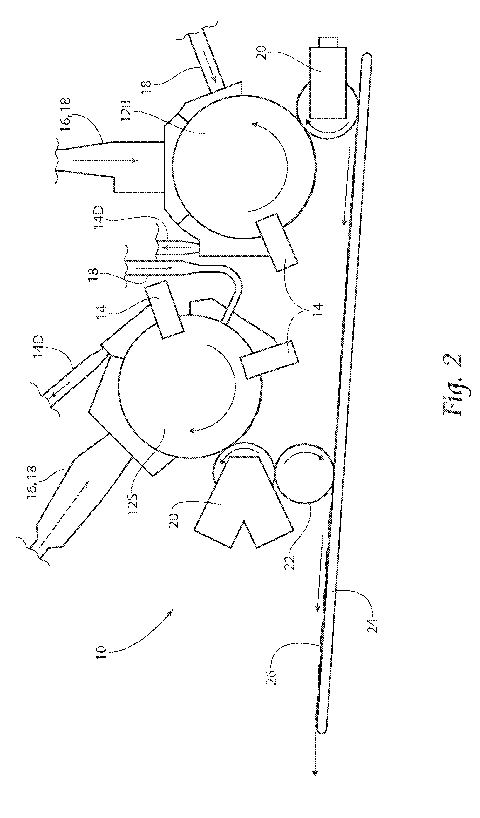
[0088]Referring now to FIG. 16, a side view of a large and small discrete core forming unit, a large and small continuous core, formed on a web is shown. The first step in the sequence of formation of both the big and small cores is introduction of a non-woven web 50. Atop this layer is applied fluff 28 by fluff introduction unit 18. Next, SAP / fluff mix 30 is applied through the SAP / Fluff introduction system 40. An optional scarfing unit 14 can be used (recycled scarf material recycled through scarf recycling pathway 14D), followed by a debulking unit 20. As can be seen in FIG. 17, the drums 12B and 12S of this system can have a continuous pocket for forming a running web of continuous core material (cut to discrete core pieces by a core knife, described later). As shown in FIGS. 18A and 18B, plan views of a big and small continuous core 46B and 46S ...

third embodiment

[0090]Referring now to FIG. 29, a schematic of the present invention, a single two or three-dimensional core formed on a screen (and / or formed on web), and then passed downstream for further processing is shown.

[0091]In this embodiment, as shown in FIG. 30, a side view of a single three-dimensional core formed on a screen core forming unit, a first fluff layer 28 from the fluff introduction unit 18 is deposited onto the drum 12 (with a three dimensional pocket, FIG. 31), followed by SAP / Fluff mixture 30 through introduction unit 16 / 18. Scarfing unit 14 is employed followed by a transfer roll 20, (debulking / embossing, or two debulking units, and an optional knife42). The scarfing unit 14 of this embodiment could scarf outer boundaries of the composite core 56 (FIG. 32), or a debulker could compress the shape by a pocket component to result in the three-dimensional, two layer profile shown in FIG. 37 (shown in plan on FIG. 38). In the embodiment of FIGS. 37 ad 38, the cores have ident...


PUM

PropertyMeasurementUnit
Lengthaaaaaaaaaa
Speedaaaaaaaaaa
Shapeaaaaaaaaaa

Abstract

Several variations of core formation techniques and machines to produced cores are disclosed, including a large and small discrete core, formed on a screen and combined; a large and small continuous core, formed on a web; and two and three-dimensional cores, formed on a screen, and core formation on a non-woven web.

Description

BACKGROUND OF THE INVENTION[0001]This invention relates to formation of absorbent cores for use in disposable products such as diapers and sanitary napkins.[0002]Sanitary napkins used in feminine hygiene are absorbent items worn by women to recover undesirable bodily discharges. These absorbent articles are typically comprised of an absorbent core sandwiched between layers of woven or non-woven materials.[0003]Generally, diapers comprise an absorbent insert or patch and a chassis, which, when the diaper is worn, supports the insert proximate a wearer's body. Additionally, diapers may include other various patches, such as tape tab patches, reusable fasteners and the like. The raw materials used in forming a representative insert are typically cellulose pulp, tissue paper, poly, nonwoven web, acquisition, and elastic, although application specific materials are sometimes utilized. Usually, most of the insert raw materials are provided in roll form, and unwound and applied in assembly...

Claims


Application Information

Patent Timeline
IPC IPC(8): A61F13/15
CPCA61F13/15764A61F13/15699
Inventor NELSON, CHRISHEINZ, COLLIN
Owner CURT G JOA
Why Eureka
Try Eureka