Tennis racket and method for manufacturing the same

Inactive Publication Date: 2013-09-19
YONEX CO LTD
View PDF9 Cites 14 Cited by
  • Summary
  • Abstract
  • Description
  • Claims
  • Application Information

AI Technical Summary

Benefits of technology

[0008]The present invention has been made in view of these circumstances, and an object thereof is to provide a tennis racket that allows improvement in rigidit

Problems solved by technology

Incidentally, since a foam material is formed uniformly inside the frame of tennis rackets such as those described above, it has been difficult to increase rigidity and vibration absorption at specific positions in the frame.
Increasing rigidity by provi

Method used


Image

  • Tennis racket and method for manufacturing the same
  • Tennis racket and method for manufacturing the same
  • Tennis racket and method for manufacturing the same

Examples


embodiments

Example of Racket Configuration

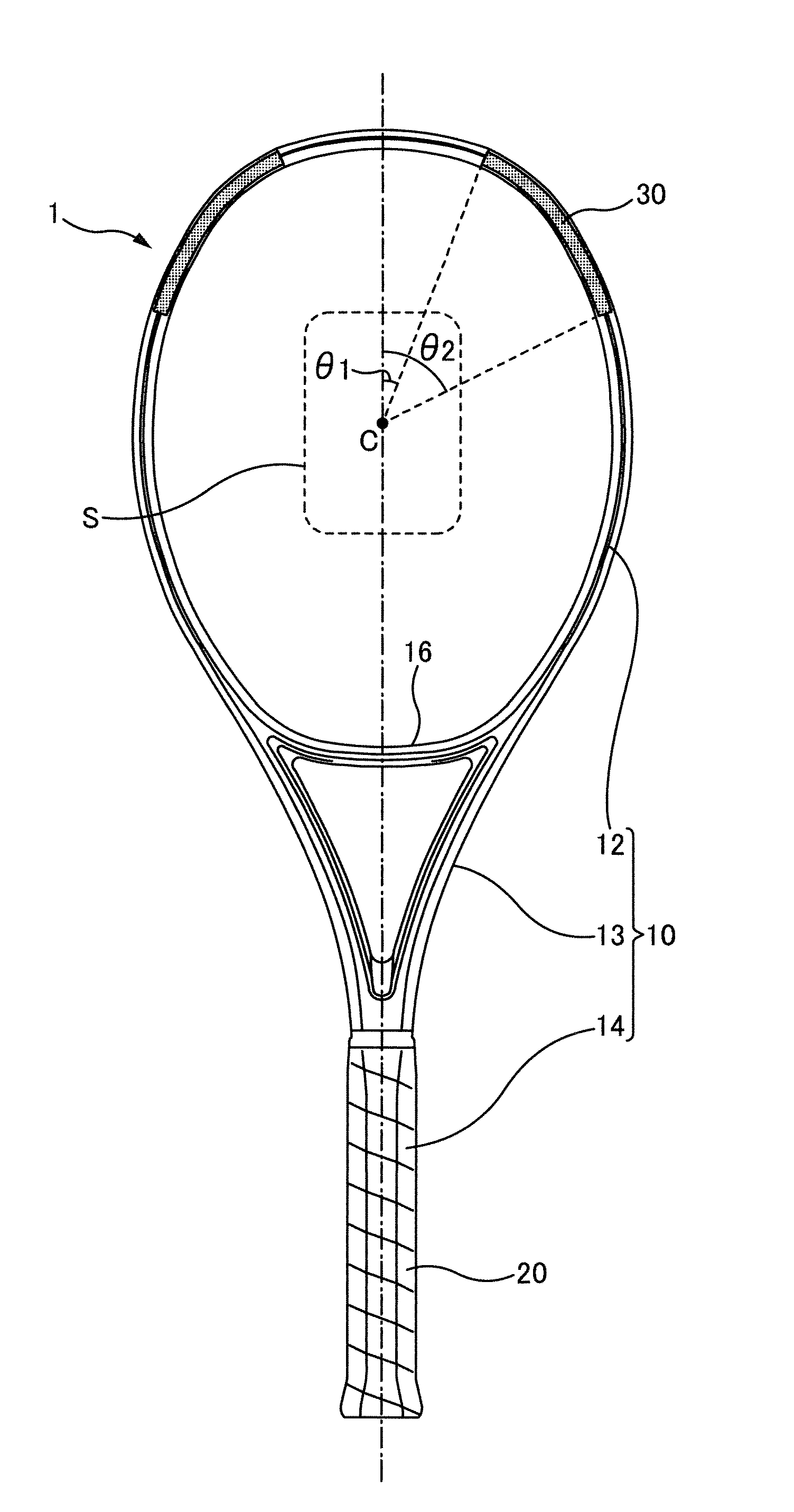
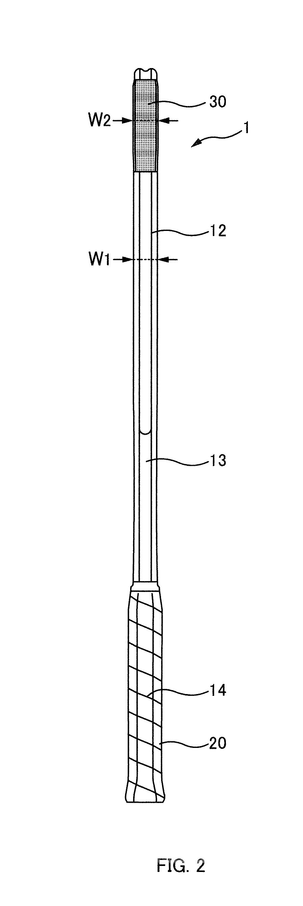
[0034]A configuration example of a tennis racket 1 according to the present invention will be described below with reference to FIGS. 1 and 2. FIG. 1 is a front view of the tennis racket 1 according to the present embodiment. FIG. 2 is a side view of the tennis racket 1 according to the present embodiment. Note that the upper side (with respect to the figure) of the tennis racket 1 shown in FIGS. 1 and 2 is called the tip side, and the lower side is called the base side.

[0035]As shown in FIG. 1, the tennis racket 1 of the present embodiment includes a frame 10 that is configured by a face portion 12 (corresponding to the frame portion), a shaft portion 13, and a grip portion 14.

[0036]The face portion 12 is provided in the top portion of the tennis racket 1 and is formed in a substantially elliptical shape. Insertion holes (not shown) for inserting a string are provided, in an inner circumferential portion and an outer circumferential portion of the fac...

embodiment

Present Embodiment

[0044]A method for manufacturing the tennis racket 1 of the present embodiment will be described below with reference to FIGS. 3A to 3D. FIGS. 3A to 3D are schematic diagrams showing the method for manufacturing the tennis racket 1.

[0045]The method for manufacturing the tennis racket 1 of the present embodiment has a foam material arranging step, a sheet tube forming step, a bending step, and a die molding step.

[0046]First, as shown in FIG. 3A, a carbon sheet 44 (which corresponds to a resin sheet) of prepreg fiber-reinforced resin (FRP) mainly made of carbon fiber is prepared, and the foam material 30 is arranged in areas that correspond to the hatched portions in FIG. 1. The foam material 30 is obtained by mixing a resin-based adhesive and a thermally expandable foam material, and forming the mixture into a sheet shape.

[0047]Note that in FIG. 3A, the midpoint of the carbon sheet 44 in the lengthwise direction (left-right direction in the figure) will become the t...


PUM

PropertyMeasurementUnit
Angleaaaaaaaaaa
Angleaaaaaaaaaa
Angleaaaaaaaaaa

Abstract

A tennis racket includes a frame that surrounds a hitting face for hitting a ball, wherein a foam material is provided inside two side portions of the frame on opposite sides of a predetermined area of the hitting face, and the two side portions of the frame have a strength that is higher than a strength of another portion of the frame.

Description

CROSS REFERENCE TO RELATED APPLICATION[0001]The present application claims priority upon Japanese Patent Application No. 2012-40538 filed on Feb. 27, 2012, which is herein incorporated by reference.BACKGROUND[0002]1. Technical Field[0003]The present invention relates to a tennis racket and a method for manufacturing a tennis racket.[0004]2. Related Art[0005]A tennis racket includes a frame that surrounds a hitting face for hitting a ball. There has also been proposed a tennis racket in which the frame is formed hollow with the entire hollow portion is uniformly filled with foam material (e.g., see Japanese Patent Application Laid-Open Publication No. 6-105923).[0006]The area of the hitting face that is frequently used differs from player to player in some cases. For example, top players (advanced players) tend to frequently use the area of the hitting face at the tip side (side opposite to the grip portion) than the substantially central portion (sweet spot). For this reason, there ...

Claims


Application Information

Patent Timeline
IPC IPC(8): A63B49/02A63B49/03A63B49/11A63B60/54A63B102/02
CPCA63B49/02A63B59/0092A63B49/027A63B49/106Y10T156/1036A63B2209/02B29L2031/5245B29C44/146B29C70/865B29C70/446A63B49/11A63B60/54A63B49/10A63B49/03
Inventor SAITO, SHINJISUETAKE, JUNYAIWASAWA, TOMOYA
Owner YONEX CO LTD
Why Eureka
Try Eureka