Seismic imaging system using cosine transform in logarithmic axis

a cosine transform and logarithmic axis technology, applied in the field of seismic imaging technology, can solve the problems of less efficient algorithms and artifacts in imaging output, and achieve the effect of improving the resolution of reverse-time migration

Inactive Publication Date: 2013-09-19
SEOUL NAT UNIV R&DB FOUND
View PDF2 Cites 3 Cited by
  • Summary
  • Abstract
  • Description
  • Claims
  • Application Information

AI Technical Summary

Benefits of technology

The patent describes a method for estimating the structure of the subsurface using a waveform inversion technique. The method involves updating the initial modeling parameters of a cosine transformed acoustic waveform equation to minimize the residual between the measured data and the modeling data. This process helps to accurately estimate the structure of the subsurface, which is important for various applications such as oil and gas exploration.

Problems solved by technology

However, reflected waves still cause artifacts in the imaging output and make the algorithms less efficient.

Method used


Image

  • Seismic imaging system using cosine transform in logarithmic axis
  • Seismic imaging system using cosine transform in logarithmic axis
  • Seismic imaging system using cosine transform in logarithmic axis

Examples


Embodiment Construction

[0017]The following description is provided to assist the reader in gaining a comprehensive understanding of the methods, apparatuses, and / or systems described herein. Accordingly, various changes, modifications, and equivalents of the methods, apparatuses, and / or systems described herein will be suggested to those of ordinary skill in the art. Also, descriptions of well-known functions and constructions may be omitted for increased clarity and conciseness.

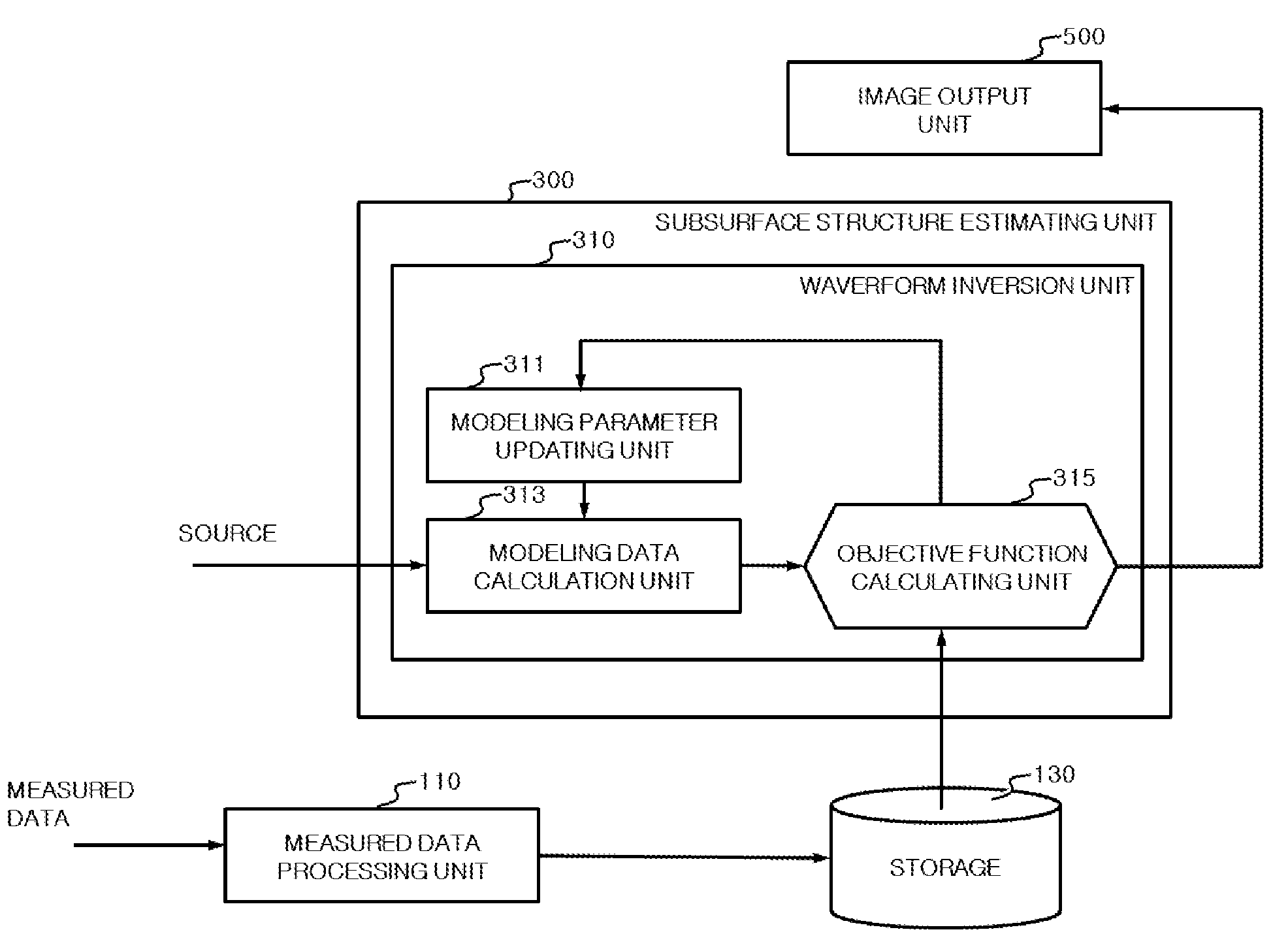
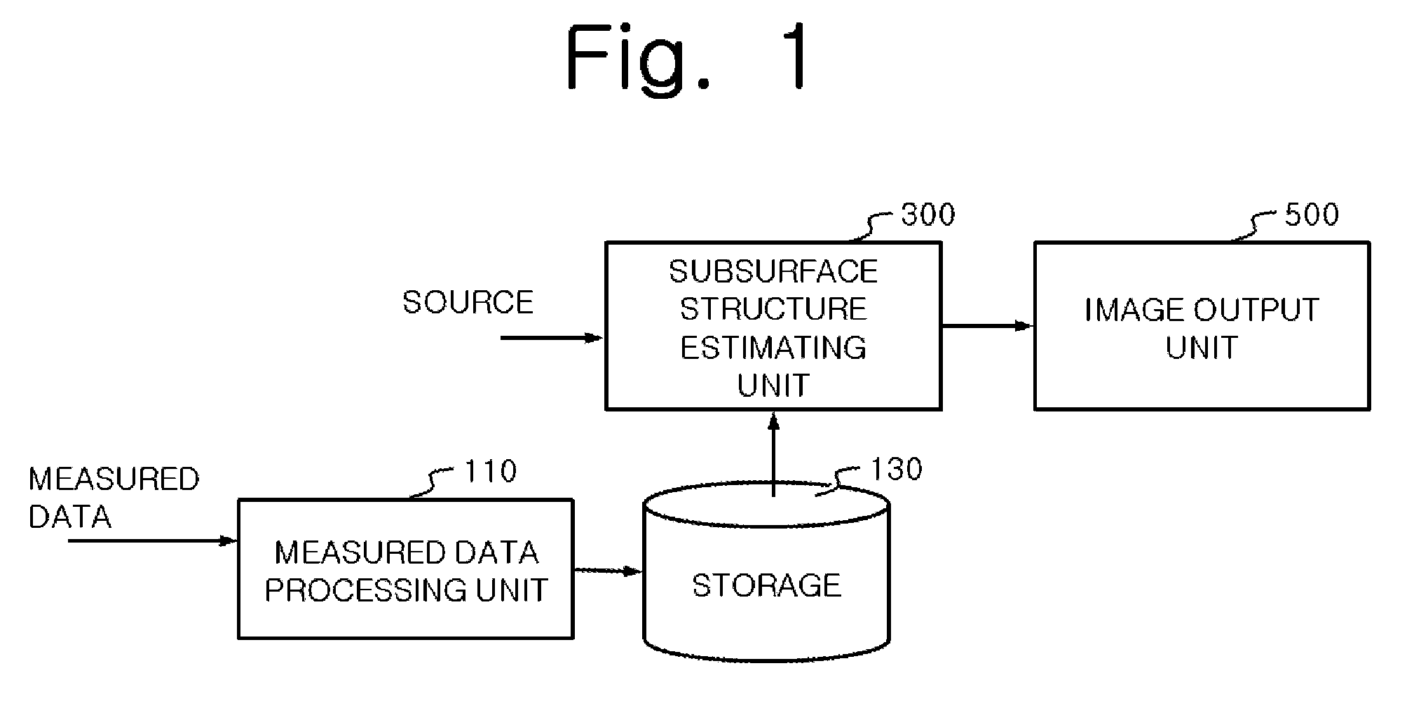
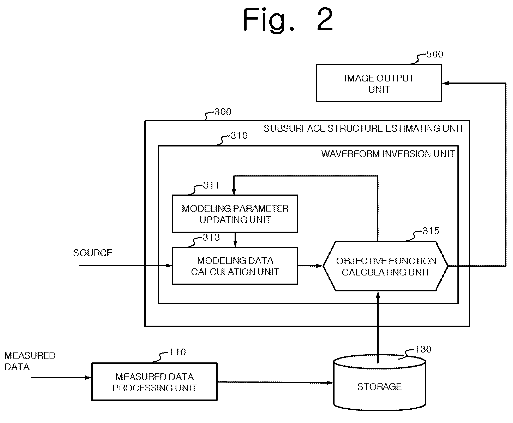
[0018]FIG. 1 is a block diagram illustrating an example of a seismic imaging system according to an exemplary embodiment. As illustrated in FIG. 1, the seismic imaging system includes a measured data processing unit 110 to convert measured data from a receiver into cosine transformed data in logarithmic scale axes and a subsurface structure estimating unit 300 to calculate subsurface modeling parameters with measured data transformed in the measured data processing unit, based on a cosine transformed acoustic waveform equation def...


PUM


Abstract

Provided is seismic imaging, particularly, a seismic imaging system. The seismic imaging system includes a measured data processing unit converting measured data from receiver to cosine transformed data in logarithmic scale axes, a subsurface structure estimating unit calculating subsurface modeling parameters with measured data transformed in the measured data processing unit based on a cosine transformed acoustic waveform equation defined along logarithmic axes, and an image output unit converting modeling parameters calculated in the subsurface structure estimating unit and outputting the converted image data.

Description

CROSS-REFERENCE TO RELATED APPLICATION[0001]This application claims the benefit under 35 U.S.C. §119(a) of a U.S. Provisional Patent Application No. 61 / 610,074, No. 61 / 610,078 and No. 61 / 610,082, all filed on Mar. 13, 2012, the entire disclosures of which are incorporated herein by reference for all purposes.BACKGROUND[0002]1. Field[0003]The following description relates to seismic imaging technology.[0004]2. Description of the Related Art[0005]Waveform inversion and reverse time migration are well known in the seismic imaging field. These algorithms are defined based on time or frequency domain. Frequency-domain based algorithms are based on Fourier-transformed measured data and a Fourier-transformed waveform equation. Another waveform inversion and migration algorithms based on Laplace-transformed measured data and a Laplace-transformed waveform equation have been proposed by inventors of the present invention, which enable the estimation of deeper parts of the subsurface with a s...

Claims


Application Information

Patent Timeline
IPC IPC(8): G01V1/00
CPCG01V1/325G01V1/003G01V2210/48G01V1/28G01V1/30
Inventor SHIN, CHANGSOO
Owner SEOUL NAT UNIV R&DB FOUND
Why Eureka
Try Eureka