Large diameter flow-through kiel-style probe for high moisture applications

a technology of flow-through kiel and probe, which is applied in the field of instruments, can solve the problems of affecting the accuracy of pressure measurements, and affecting the accuracy of measuring total pressure in a wet-steam environmen

Active Publication Date: 2013-09-26
GENERAL ELECTRIC CO
View PDF8 Cites 4 Cited by
  • Summary
  • Abstract
  • Description
  • Claims
  • Application Information

AI Technical Summary

Problems solved by technology

Measuring total pressure in a wet-steam environment, however, is often hampered by the development of water “legs” in the pressure tubing.
Without this information, it is impossible to recalculate the correct

Method used


Image

  • Large diameter flow-through kiel-style probe for high moisture applications
  • Large diameter flow-through kiel-style probe for high moisture applications
  • Large diameter flow-through kiel-style probe for high moisture applications

Examples


Embodiment Construction

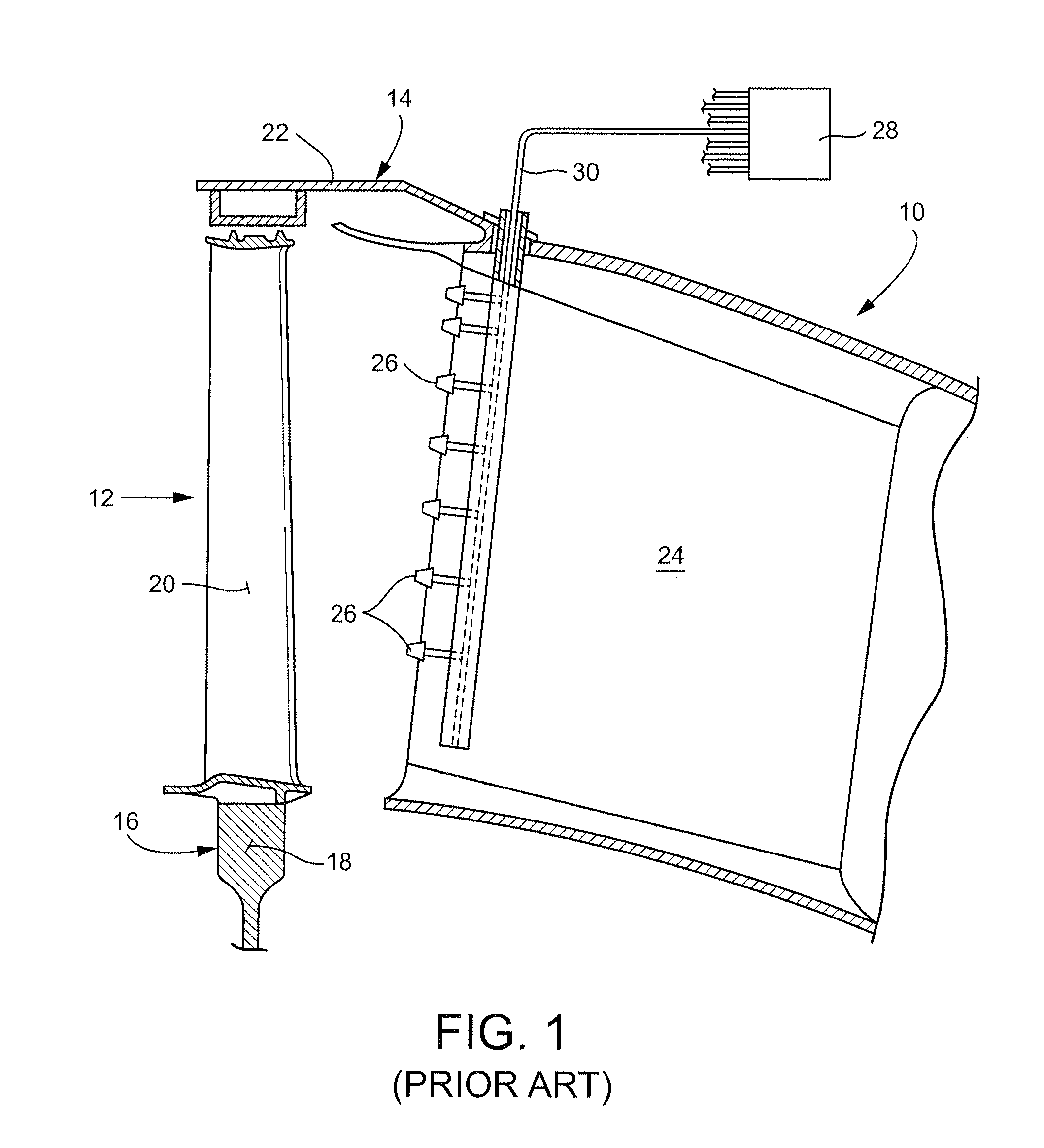
[0016]FIG. 1 is a simplified cross-section of a last-stage turbine section as described as disclosed in U.S. Pat. No. 4,433,584, illustrating a known arrangement of a pressure probe rake located in the turbine exhaust. More specifically, the engine has a turbine section 10 (partially shown) and a flow path 12 for process gases which flow axially through the turbine section to the exhaust duct. The turbine section 10 has a stator assembly14 and a rotor assembly 16. The rotor assembly includes a rotor disk 18 fitted with a plurality of radially-outwardly extending blades or buckets as represented by the single bucket 20. The stator assembly includes an outer casing 22 which circumscribes the turbine section and flow path. In this example, a plurality of stator struts 24 (one shown) extend radially inwardly from the outer casing across the flow path. The strut 24 has a plurality of total pressure probes 26 incorporated into the strut. Each total pressure probe 26 is in fluid communicat...


PUM


Abstract

A Kiel-style pressure probe includes pressure tubing having a remote sending end, the pressure tubing extending through an open-ended shroud, wherein the shroud has a diameter of at least about 0.375 to 0.50 inch and wherein a forward end of the shroud is formed with at least two drainage apertures in proximity to the remote sensing tip of the pressure tubing.

Description

BACKGROUND OF THE INVENTION[0001]The present invention relates generally to instrumentation used in turbine power plants and development test turbines and, more specifically, to a total-pressure probe effective in high-moisture conditions.[0002]Total-pressure probes are often used to measure total pressure in a fluid environment where the direction of flow is not known or changes with operating conditions. Kiel-style probes have a straight flow-through design and are typically installed on cylindrical rake masts. These probes are mounted at various radial locations across a flow path, and pressure tubing is routed through the rake mast to a transducer where the pressure measurement is translated to a signal for routing to a data acquisition system.[0003]The Kiel-style probe is a pitot-style probe but has a shroud to protect the pressure tubing. The shroud makes the probe insensitive to a range of yaw and pitch angles because the flow is straightened as it enters the probe. Kiel-styl...

Claims


Application Information

Patent Timeline
IPC IPC(8): G01F1/46
CPCG01L19/00G01L7/00
Inventor WATKINS, TONYA LYNNSNIDER, ZACHARY JOHNCOLE, TARA ASHLEY
Owner GENERAL ELECTRIC CO
Why Eureka
Try Eureka