Front vehicle body structure

a front vehicle and body technology, applied in the direction of roofs, bumpers, transportation and packaging, etc., can solve the problems of no means, reduced impact absorbing capacity, so as to increase the ability to absorb impact and increase the impact absorbing capacity

Active Publication Date: 2013-09-26
HONDA MOTOR CO LTD
View PDF18 Cites 36 Cited by
  • Summary
  • Abstract
  • Description
  • Claims
  • Application Information

AI Technical Summary

Benefits of technology

[0010]In view of the foregoing prior art problems, it is an object of the present invention to provide an improved front vehicle body structure which, at the time of occurrence of an offset collision of a narrow abutment width, can achieve an increased capability for absorbing an impact of a frontal collision load, and which, in a case where a connection member, such as a gusset, is provided to increase the impact absorbing capability, can prevent the connection member from peeling off easily.

Problems solved by technology

However, the front vehicle body structure disclosed in patent literature 1 includes no means for positively transmitting a frontal collision load, acting on the outer bumper beam extension and lower member, for example from the lower member to the front side frame.
Thus, when a narrow offset collision has occurred, the frontal collision load would be received by members disposed laterally outward of the side frame, and thus, an impact absorbing capability would be considerably limited.
However, when a narrow offset collision has occurred only within a narrow range laterally outward of the front side frame, it would be difficult for the inner bumper beam extension to take part in absorption of a frontal collision load.
Thus, when a frontal collision acts on the outer bumper beam extension, it would be difficult for the inner bumper beam extension to take part in impact absorption.
Furthermore, in the front vehicle body structure disclosed in patent literature 1, a distal end portion of the front side frame has a width increasing toward the front of the vehicle body as viewed in plan, and thus, a space between the front side frame and the lower member is so small that it would be difficult to mount other component parts within the space.
However, increasing the rigidity of the laterally outer end portions of the front section of the vehicle body cannot secure sufficient impact absorbing performance at the time of occurrence of a narrow offset collision involving a frontal collision load.

Method used


Image

  • Front vehicle body structure
  • Front vehicle body structure
  • Front vehicle body structure

Examples


Embodiment Construction

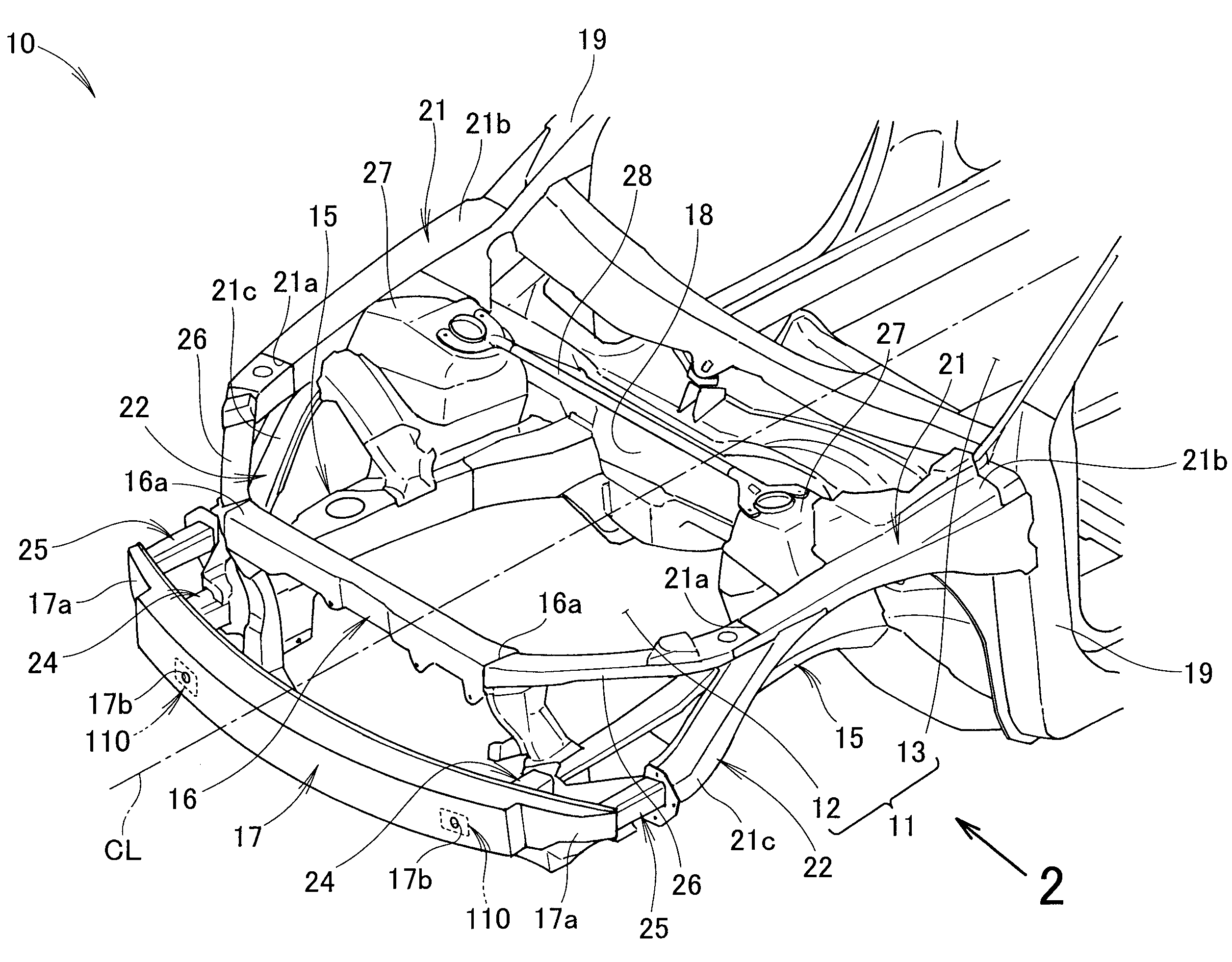
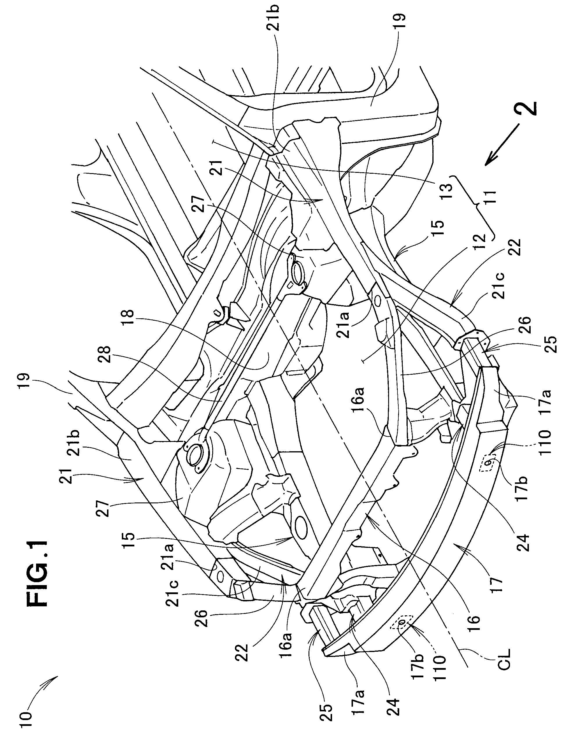
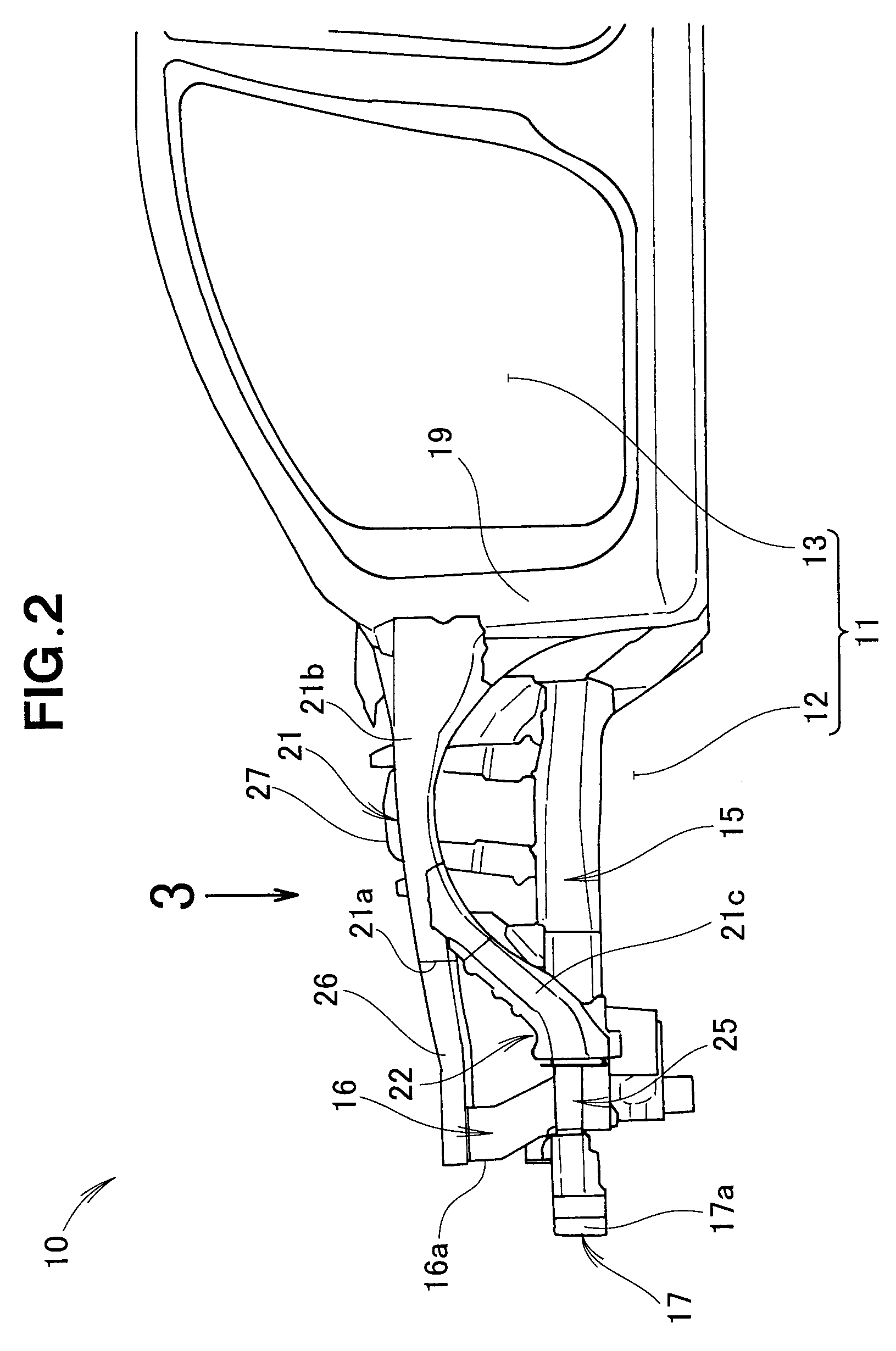
[0060]As shown in FIGS. 1 to 4, an embodiment of a front vehicle body structure of the present invention is constructed to behave advantageously at against a narrow offset collision of the vehicle by including, on each of left and right sides thereof, a front side frame 15, a lower member 22; a gusset (lower member connection member) 31, an inner bumper beam extension (hereinafter sometimes referred to also as “inner extension”) 24, an outer bumper beam extension (hereinafter sometimes referred to also as “outer extension”) 25, a tension member (mounting plate member) 32 and a vertically-oriented reinforcing member 44 on each of left and right sides of the vehicle body.

[0061]In the embodiment of the front vehicle body structure, the tension member 32 extends between and interconnects the distal end 15a of the front side frame 15 and the gusset (lower member connection member) 31 so that, at the time of occurrence of a narrow offset collision, it can transmit a load from the gusset 3...


PUM


Abstract

On each of left and right sides of a vehicle body, a gusset is provided spaced in a rearward direction of a vehicle body from the distal end of a front side frame by a predetermined distance, a tension member extends between and interconnects the distal end of the front side frame and an outer end portion of the gusset so as to prevent the gusset from peeling off the front side frame, and a mounting plate spans between and interconnects the respective front ends of an inner bumper beam extension extending forward from the front end of the front side frame and an outer bumper beam extension extending forward from the front end of an upper member. A bumper beam is joined to the mounting plates on the left and right sides of the vehicle body.

Description

FIELD OF THE INVENTION[0001]The present invention relates to a front vehicle body structure which includes left and right front side frames extending in a front-rear direction of the vehicle body, and left and right gusset disposed laterally outward (i.e., outward in a vehicle width direction) of the corresponding front side frames for transmitting a frontal collision load to the front side frames, and which also includes left and right bumper beam extensions extending forward toward the front of the vehicle body from the respective front ends of the left and right front side frames and left and right upper members.BACKGROUND OF THE INVENTION[0002]In the conventionally-known front vehicle body structures, a front side frame extends in a front-rear direction of the vehicle body, a lower member is disposed laterally outward (i.e., outward in a vehicle width direction) of the front side frame and extending substantially parallel to the front side frame as viewed in plan, an inner bumpe...

Claims


Application Information

Patent Timeline
Patent Type & Authority Applications(United States)
IPC IPC(8): B62D21/15
CPCB62D21/152B62D25/082B60R19/34
Inventor SEKIGUCHI, TOMOHIDETAGUCHI, YOSHINORIKONISHI, TAKANORI
Owner HONDA MOTOR CO LTD
Why Eureka
Try Eureka