Wearable device with input and output structures

a wearable device and input and output technology, applied in the field of video or image displays, can solve the problems of obstructing the wearer's vision, blacking out devices, and many limitations of devices

Inactive Publication Date: 2013-09-26
GOOGLE LLC
View PDF20 Cites 64 Cited by
  • Summary
  • Abstract
  • Description
  • Claims
  • Application Information

AI Technical Summary

Benefits of technology

[0007]The band can include a compliant inner portion and a resilient outer portion. The resilient outer portion can be a substantially uniform structure and the compliant inner portion can line the resilient outer portion. Further, the end of the first side arm can be elongated relative to the free of the second side arm to form an asymmetric U shape. The end of the first side arm can be further enlarged relative to the end of the second side arm with such an enlarged end housing at least one of circuitry and a power source employed by the display device. The asymmetric U shape can provide multiple points of contact for the user's head, and the enlarge end of the first side arm can provide a balancing weight relative to the extension arm. The enlarged end can include a plurality of electrical contacts to connect an external device with the at least one of circuitry and a power source. The electrical contacts can be substantially flush with an exterior surface of the enlarged end and can be separated by a portion of the exterior surface.

Problems solved by technology

Regardless of the type of image presented to the user, such devices are usually blacked-out.
That is, they almost entirely obstruct the wearer's vision outside of the screen or other image source included therein so that the user can see nothing but the image presented by the device's display system.
Such devices, however, can have many limitations, including in their fit and comfort to their wearers as well as limited functionality.
The functionality of these types of displays is, however, limited to passive actions wherein the display simply receives information from an external source and presents it to the wearer in limited forms.

Method used


Image

  • Wearable device with input and output structures
  • Wearable device with input and output structures
  • Wearable device with input and output structures

Examples


Embodiment Construction

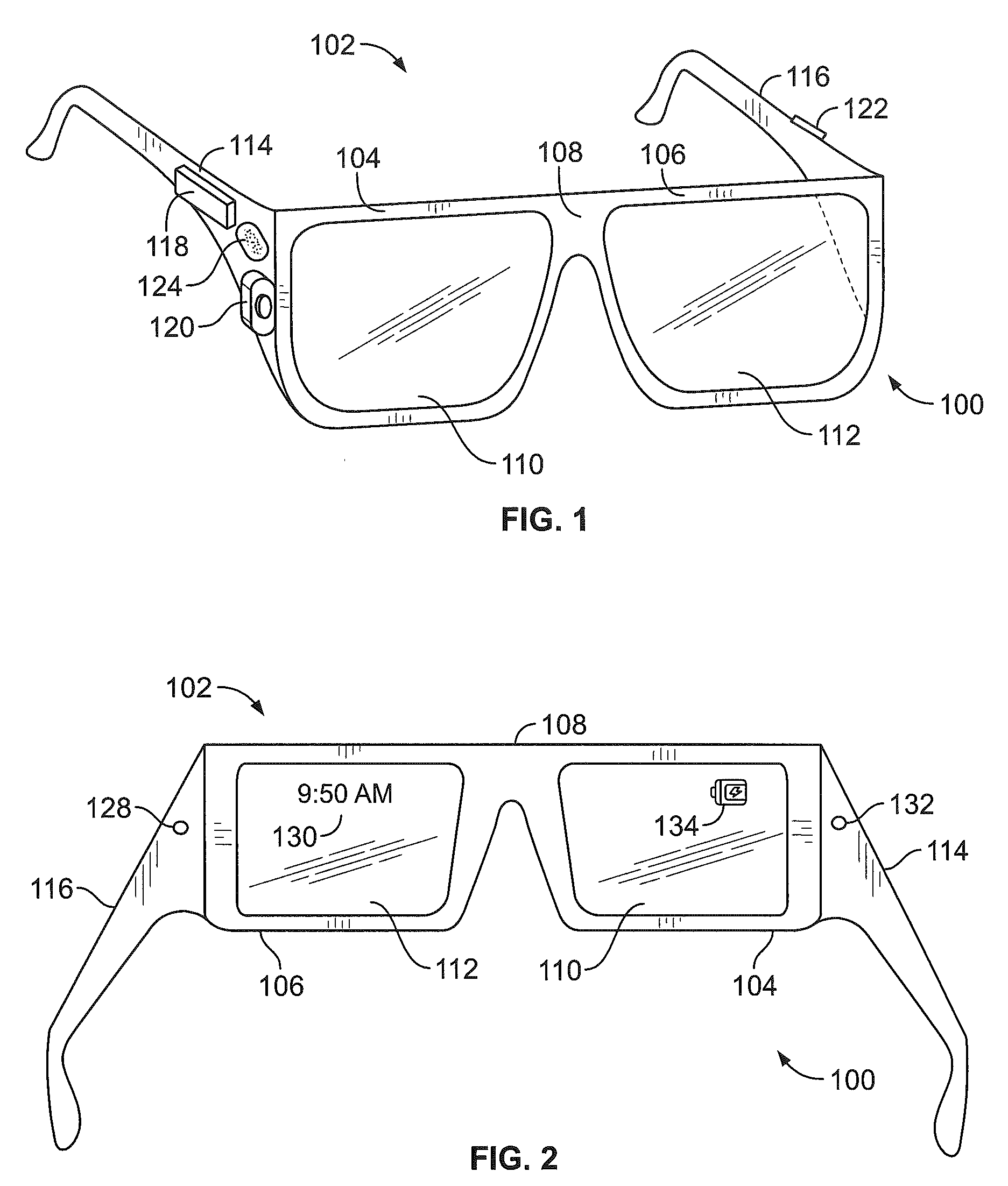
[0025]Embodiments of the present disclosure are described herein with reference to the drawing figures. FIG. 1 illustrates an example system 100 for receiving, transmitting, and displaying data. The system 100 is shown in the form of a wearable computing device. While FIG. 1 illustrates a head-mounted device 102 as an example of a wearable computing device, other types of wearable computing devices could additionally or alternatively be used. As illustrated in FIG. 1, the head-mounted device 102 comprises frame elements including lens-frames 104, 106 and a center frame support 108, lens elements 110, 112, and extending side-arms 114, 116. The center frame support 108 and the extending side-arms 114, 116 are configured to secure the head-mounted device 102 to a user's face via a user's nose and ears, respectively.

[0026]Each of the frame elements 104, 106, and 108 and the extending side-arms 114, 116 may be formed of a solid structure of plastic and / or metal, or may be formed of a hol...


PUM


Abstract

A head-wearable device includes a center support extending in generally lateral directions, a first side arm extending from a first end of the center frame support and a second side arm extending from a second end of the center support. The device further includes an extension arm configured to present information to the user via a display element. The extension arm extends at least partially along the first side arm on a first side of the center support and further extends from the first side arm to a display end that supports the display element in a position on a second side of the center support. The extension arm has a joint therein configured for movement of the display element at least in a direction having a lateral component relative to the center support.

Description

BACKGROUND[0001]Personal video or image displays are devices that are used to display an image received from a source for viewing by a single user. Such devices can be in the form of head-mounted displays that are worn on the head of a user and include one or more image sources over or in front of the user's eyes. Head-mounted displays can include an image source positioned adjacent and associated with each eye of the user or wearer and can be configured to present the same image, viewable as a single two-dimensional image. Alternatively, some such devices can be configured to present different stereoscopic images that are interpreted by the viewer as a single three-dimensional image. Regardless of the type of image presented to the user, such devices are usually blacked-out. That is, they almost entirely obstruct the wearer's vision outside of the screen or other image source included therein so that the user can see nothing but the image presented by the device's display system.[0...

Claims


Application Information

Patent Timeline
Patent Type & Authority Applications(United States)
IPC IPC(8): G09G5/00
CPCG06F1/163G02C11/10G02B27/0176G02B2027/0178G02B27/0101G02B27/0149G02B27/0172G02B2027/0138G02B2027/0159G02C3/003
Inventor OLSSON, MAJ ISABELLEMARTIN, MATTHEW WYATTHEBENSTREIT, JOSEPH JOHNCAZALET, PETER MICHAEL
Owner GOOGLE LLC
Why Eureka
Try Eureka