
Arrangement for connecting to network in network system

a network system and network configuration technology, applied in the field of network systems, can solve the problems of human-readable display of connection information, considered undesirable,

Active Publication Date: 2013-09-26
RICOH KK
View PDF8 Cites 72 Cited by
  • Summary
  • Abstract
  • Description
  • Claims
  • Application Information

AI Technical Summary

Benefits of technology

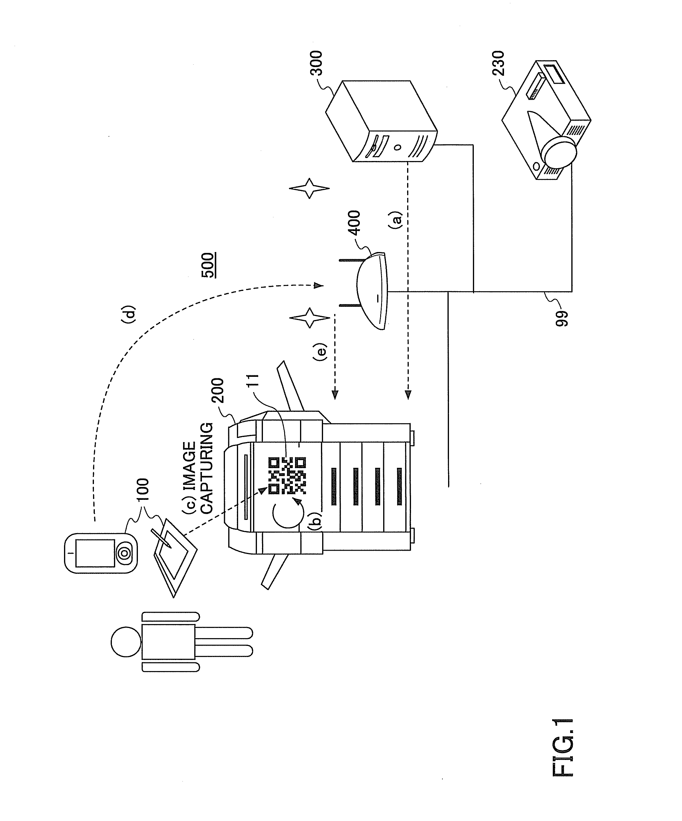
The present invention relates to a network system that allows a server to connect a portable terminal to a network, and the server to send connection information to the portable terminal. The portable terminal then displays the connection information using an image code, which is decoded by another portable terminal connected to the network. The portable terminal sends a job request to the server, which then executes the job based on the request. The technical effects of this invention are that it simplifies the process of connecting a portable terminal to a network, reduces the risk of security vulnerabilities, and provides a more seamless user experience.

Problems solved by technology

However, in order to establish a connection to a network, it is necessary to do some setup in the portable terminal except in the case of a special network that is open to an unspecified number of users.
However, it is considered undesirable for security reasons to display connection information in a human readable manner.

Method used


Image

  • Arrangement for connecting to network in network system
  • Arrangement for connecting to network in network system
  • Arrangement for connecting to network in network system

Examples


example configuration

[Example Configuration]

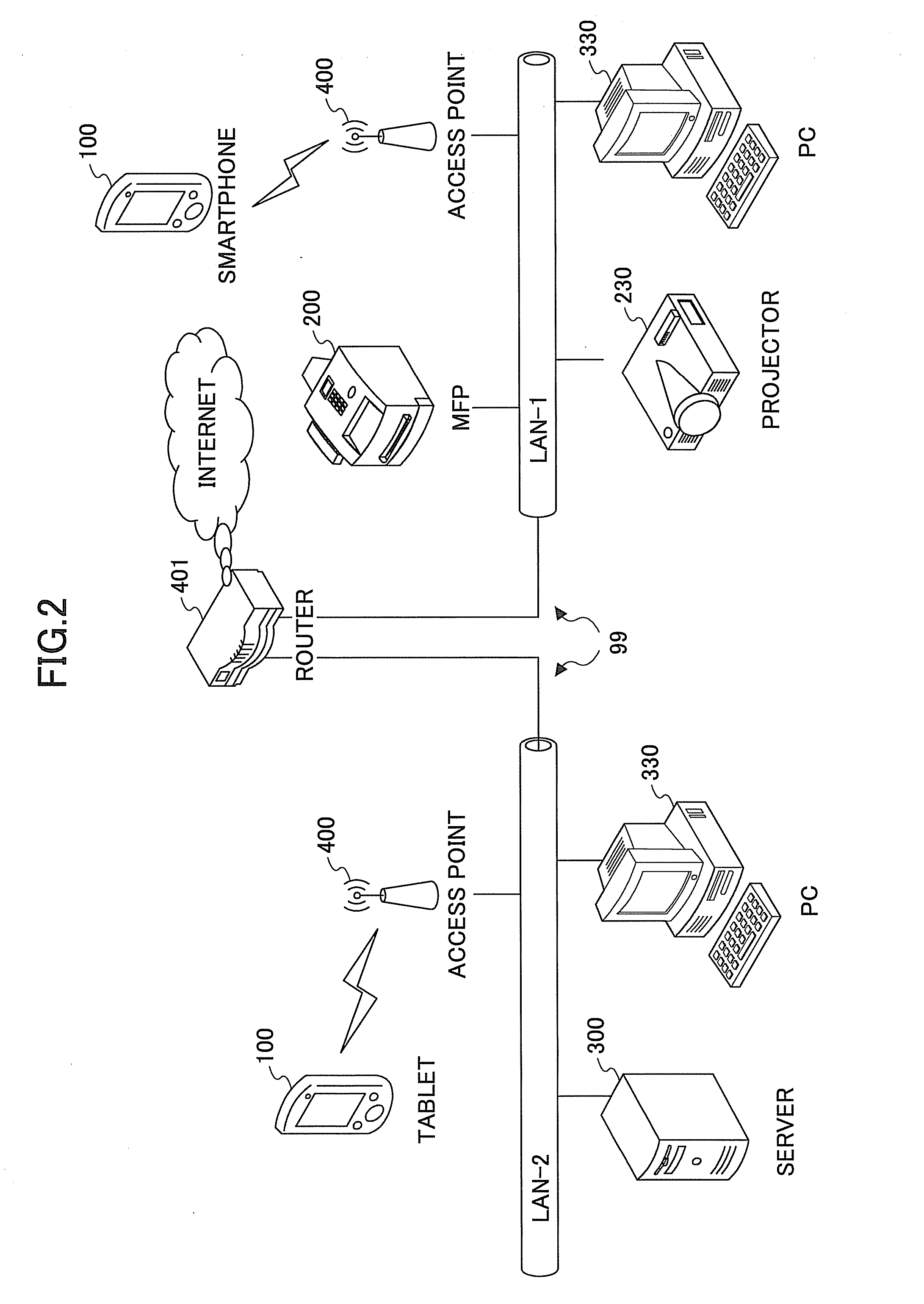
[0050]FIG. 2 is a schematic diagram illustrating a configuration of the network system 500 of this embodiment. The server 300, personal computer (PC)s 330 (hereinafter also collectively referred to as the “PC 330”), the MFP 200, and the projector 230 are stationary apparatuses connected in advance to a LAN-1 or LAN-2 (and are hereinafter referred to as “apparatuses” when they are not distinguished). Each of the apparatuses is connected to the LAN-1 or LAN-2 by wire, but may be connected wirelessly to the LAN-1 or LAN-2 via the access point 400.

[0051]The network system 500 includes two LANs, that is, the LAN-1 and the LAN-2, and the LAN-1 and the LAN-2 are connected to each other via a router 401. The access point 400 is provided in each of the LAN-1 and the LAN-2, and the portable terminal 100 connects to the LAN-1 or the LAN-2 via the access point 400. The access point 400 may be provided in either the LAN-1 or the LAN-2. Multiple access points 400 may be pro...


PUM


Abstract

A network system includes a server and an apparatus connected to the server via a network. The server includes a connection information generation part configured to generate connection information including network connection information for a portable terminal connecting to the network and apparatus connection information including the IP address of the apparatus, and a connection information transmission part configured to transmit the connection information to the apparatus. The apparatus includes an image code display part configured to display an image code into which the connection information is converted, a request reception part configured to receive a job request specifying the IP address of the apparatus and transmitted from the portable terminal having decoded the image code and connected to the network using the network connection information, and a job execution part configured to execute a job based on the job request.

Description

CROSS-REFERENCE TO RELATED APPLICATION[0001]The present application is based upon and claims the benefit of priority of Japanese Patent Application No. 2012-064478, filed on Mar. 21, 2012, the entire contents of which are incorporated herein by reference.BACKGROUND OF THE INVENTION[0002]1. Field of the Invention[0003]The present invention relates to a network system in which an apparatus and a server are connected via a network.[0004]2. Description of the Related Art[0005]It is often the case that a user who is out of office on a business trip or the like wishes to connect a terminal that the user carries to a network. Once the connection to the network is established, it is possible to use a cloud service or to access an office server and use a stored document by connecting to, for example, the Internet.[0006]However, in order to establish a connection to a network, it is necessary to do some setup in the portable terminal except in the case of a special network that is open to an ...

Claims


Application Information

Patent Timeline
IPC IPC(8): H04L29/06
CPCH04L67/14H04L65/1069G09G2370/025
Inventor SUZUKI, RYOICHI
Owner RICOH KK
Learn More