Information reception device, information transmission system, and information reception method

a technology of information transmission system and information reception device, which is applied in the field of information reception device, information transmission system and information reception method, can solve the problems of wasteful image processing, inaccurate extraction of information from optical tag unit, and inconvenient so as to accelerate information decoding processing and facilitate the effect of position adjustment of optical modulation region

Inactive Publication Date: 2006-10-26
CASIO COMPUTER CO LTD
View PDF9 Cites 133 Cited by
  • Summary
  • Abstract
  • Description
  • Claims
  • Application Information

AI Technical Summary

Benefits of technology

[0012] Therefore, the purposed of the present invention is to provide an information reception device, information transmission system and information reception method which aims at accelerating information decoding processing by acquiring the region essential for detection of optical modulation from among the capturing angles. Furthermore, the present invention aims at making the position adjustment of the optical modulation region easy.
[0028] Also, the present invention may further comprise a light reception direction portion to direct light reception of the optical region specified by the specification portion and a control portion to control the light reception portion so that the optical axis matches the optical modulation region when directed by the light reception direction portion. Thus, alignment of the region can be accomplished more easily.
[0034] Thus, acquisition of an image and reproduction of information can be carried out in separate time intervals, whereby more efficient processing can be attained. Additionally, in this manner when unsuccessful in acquisition of information, only reacquisition of information can be performed without acquiring an image. Thus, wasteful image acquisition can be avoided and increased efficiency can be promoted.

Problems solved by technology

However, when someone wants to look for a specific information notice in an environment with a lot of information presentation signs, a problem occurs in that the information notice is not conspicuous with the surrounding information presentation signs.
However, in this conventional prior art 1, there exists a technological problem in that extraction of the optical tag unit information cannot be performed accurately, for example, when there is a light source (for example, disturbance light, such as flicker of a fluorescent light) in the vicinity which is prone to optical variations by the same pattern as the optical variation pattern of a blinking optical tag unit.
However, in the conventional prior art 2, although the adverse influence by disturbance light can be avoided, there is a problem with wastefulness in processing an image.
In other words, this method is none other than performing detection and capture of the point light source pertaining to all regions of an image within the capture angle of the image sensor.
Therefore, as explained below, wasteful processing cannot be refused.
However, the visual recognition size of the point light source located at a distance, namely, the point light source of the light emitting unit, is considerably small.
Thus, processing is inefficient for the other divided areas which do not include a point light source.

Method used


Image

  • Information reception device, information transmission system, and information reception method
  • Information reception device, information transmission system, and information reception method
  • Information reception device, information transmission system, and information reception method

Examples


first embodiment

A. First Embodiment

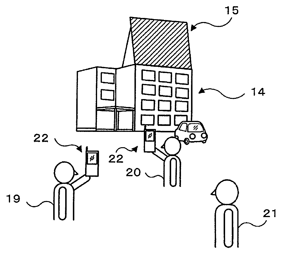
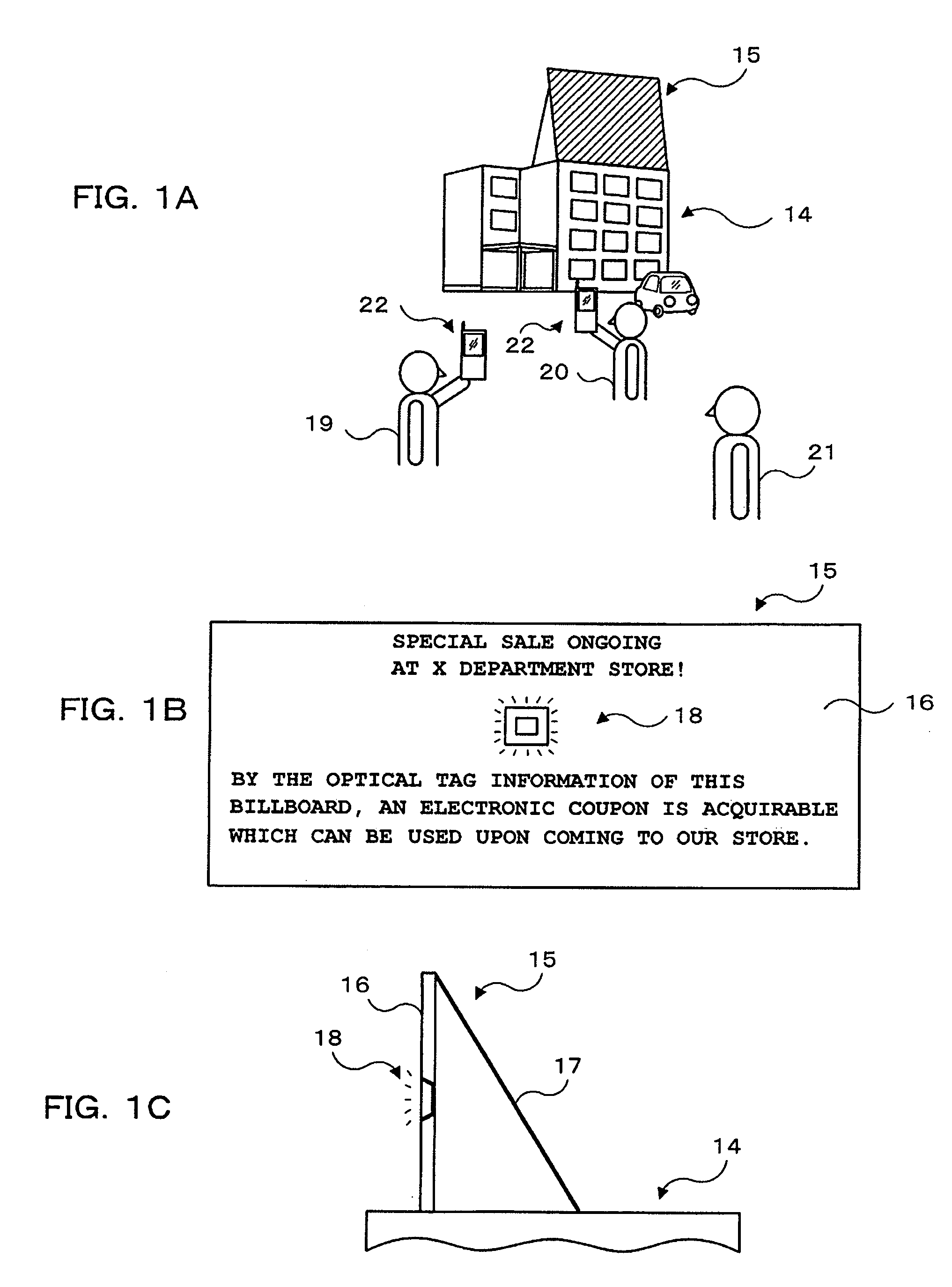
[0072] FIGS. 1A˜1C are usage status diagrams of an information transmission system in the first embodiment. First, FIG. 1A illustrates an advertisement display board 15 installed on the roof of a structure 14, such as a building. In FIG. 1B, this advertisement display board 15 is shown in a front elevation view and FIG. 1C shows a side view. The billboard 16 depicts a large optional description character string (In FIG. 1B, “SPECIAL SALE ONGOING AT X DEPARTMENT STORE!”, “BY THE OPTICAL TAG INFORMATION OF THIS BILLBOARD, AN ELECTRONIC COUPON IS AQUIRABLE WHICH CAN BE USED UPON COMING TO THE STORE.”). As shown in FIG. 1C, a back stationary reinforcement 17 supports the billboard 16 from behind. From a distance, the descriptive character string can be visually identified.

[0073] An optical tag unit 18 is mounted in an optional position of the billboard 16 (substantially the center portion in the example illustration). The optical tag unit 18 is a point light source w...

second embodiment

B. Second Embodiment

[0163] Apart from the above, although in the above-mentioned first embodiment the photodetector 61 is used as a light reception means for light reception of the luminescent spot of the optical tag unit 18, the present invention is not restricted to this. What is necessary is to have an angle of view corresponding to the size of the information offering object (the optical tag unit 18). For example, this may be an image sensor, such as a CCD, CMOS, etc., or a plurality of photodetectors arranged on a plane surface.

[0164] Hereinafter, the second embodiment using an image sensor, such as a CCD, CMOS, etc, will be explained.

[0165]FIG. 25 is an internal block configuration diagram of the camera cell-phone 220 in the second embodiment. As shown in FIG. 25, the camera cell-phone 220 has the feature point of comprising an image sensor for communication 610 in place of the image sensor 57 of the photodetector 61 in the above-described first embodiment (hereinafter, also...


PUM


Abstract

An information reception device comprising an imaging portion; a light reception portion for light reception of optional information subjected to optical modulation; a specification portion for specifying an optical modulation region contained in a capture angle of the imaging portion; a decoding portion for controlling the light reception portion in order to carry out light reception of the optical modulation region specified by the specification portion and decoding the optional information from the optical modulation content contained in the region; and a reproduction portion for reproducing the optional information decoded by the decoding portion. By acquiring a region essential for detection of optical modulation, acceleration of the information decoding process is achieved. Furthermore, position adjustment of the optical modulation region is easily accomplished.

Description

[0001] This is a Continuation Application of PCT application No. PCT / JP2005 / 010290 filed on May 30, 2005.TECHNICAL FIELD [0002] The present invention relates to an information reception device, information transmission system and information reception method which can be ideally used for various purposes, for example, a landmark display for a building, etc.; an advertisement display; recreational facility information or congestion situation of an amusement park, etc.; description of an item in a store window; explanation of an exhibit in a museum or public show, etc. BACKGROUND ART [0003] In the past, a landmark display for a building, etc.; an advertisement display; recreational facility information or congestion situation of an amusement park, etc.; description of an item in a store window; explanation of an exhibit in a museum or public show, etc. has been performed using “visual information,” such as characters, graphic symbols, etc., written on “information presentation signs,”...

Claims


Application Information

Patent Timeline
Patent Type & Authority Applications(United States)
IPC IPC(8): G03B17/18G03B7/091H04B10/00H04B10/11H04B10/116H04B10/54H04B10/556H04M1/21H04M1/2755H04N5/225H04N5/232H04N7/14
CPCH04B10/1125H04M1/2755H04N2007/145H04N5/23293H04N7/142H04M2250/52H04N23/634H04N23/635H04B10/11H04M1/21H04B10/60
Inventor IIZUKA, NOBUONAGATOMO, SHOICHI
Owner CASIO COMPUTER CO LTD
Why Eureka
Try Eureka