Light bar-combined removable zipper

Inactive Publication Date: 2013-09-26
KINGS METAL FIBER TECH
View PDF2 Cites 0 Cited by
  • Summary
  • Abstract
  • Description
  • Claims
  • Application Information

AI Technical Summary

Benefits of technology

The present invention provides a removable zipper that combines a light bar and is easy to assemble and remove. It is resistant to water, can emit light for alarming purposes, and can be controlled for light emission and flashing to improve its convenience of use. No irradiation of light is required for generating light reflection for alarming purposes.

Problems solved by technology

Further, in the daytime, due to the over-sufficiency of the ambient light, the reflected light from the light-reflective zipper cannot be easily noted and again, there will be of no prominent alarm effect.

Method used


Image

  • Light bar-combined removable zipper
  • Light bar-combined removable zipper
  • Light bar-combined removable zipper

Examples


first embodiment

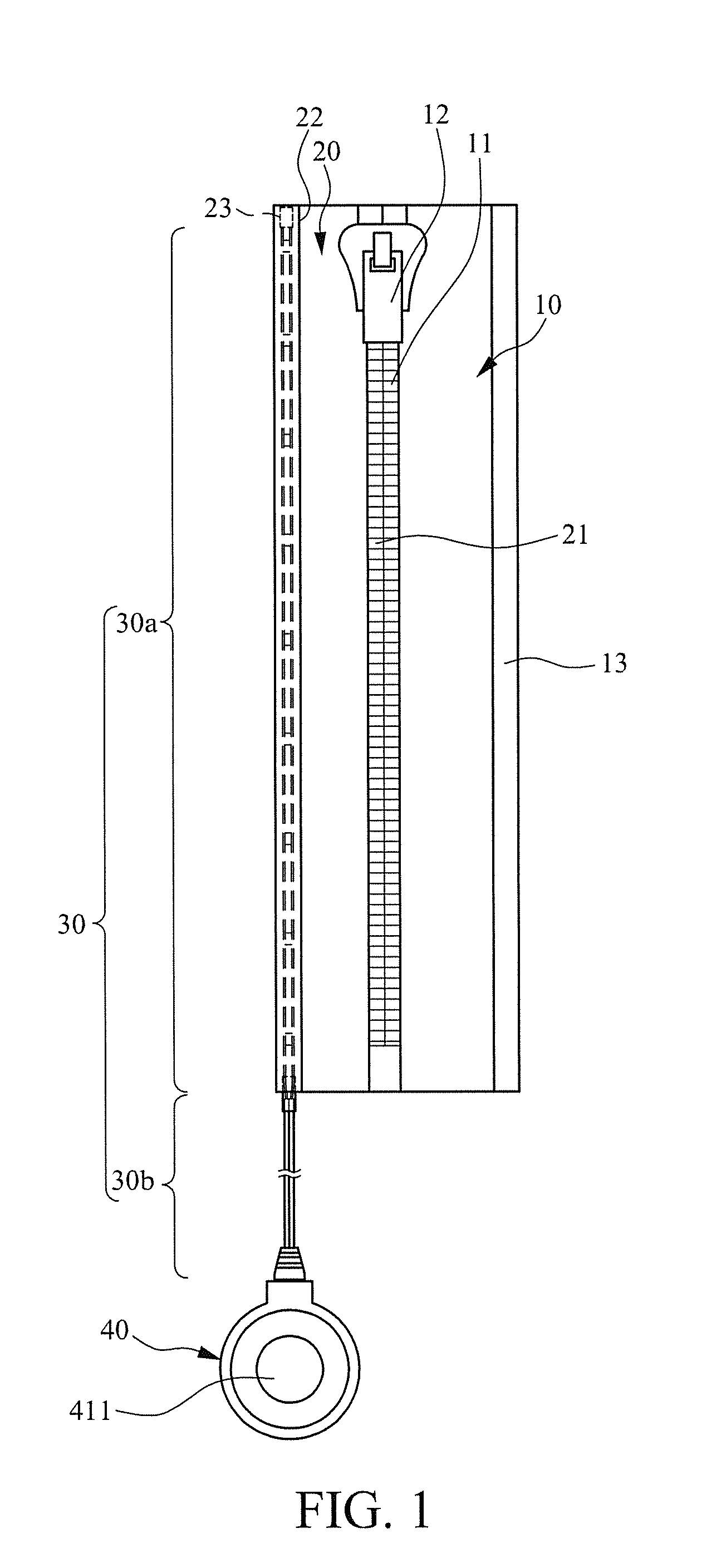
[0016]Referring to FIGS. 1-6, a light bar-combined removable zipper according to the present invention comprises a first tape 10, a second tape 20, a light bar 30, and a controller 40. The second tape 20 has an edge that is joinable to an edge of the first tape 10 to constitute the removable zipper. The light bar 30 is combined to the second tape 20. The controller 40 is connected to the light bar 30 to supply electrical power to and selectively activate / deactivate the lighting of the light bar 30.

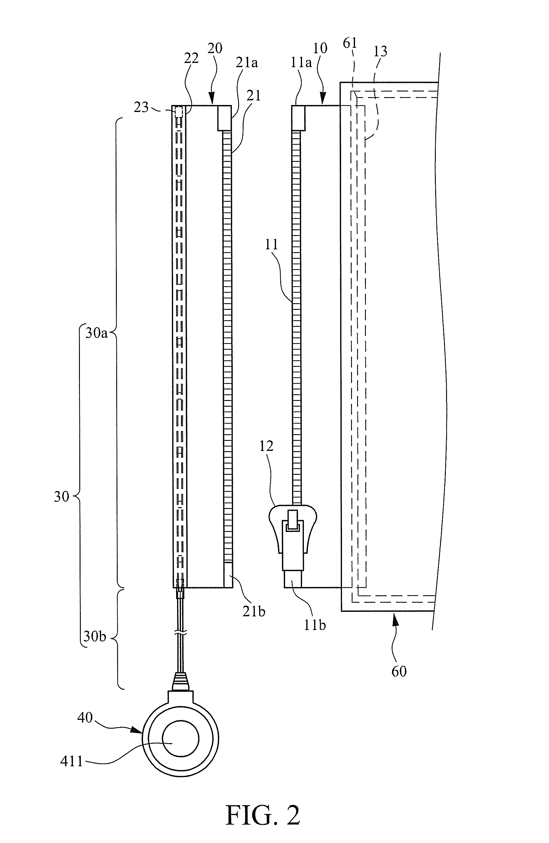
[0017]In the first embodiment, as shown in FIG. 2, the first tape 10 comprises an edge to which a first tooth row 11 and a first slider 12 are mounted. The first slider 12 is movably coupled to and reciprocally slidable along the first tooth row 11. The first tooth row 11 has two opposite ends to which stops 11a, 11b are respectively mounted to prevent the first slider 12 from undesired separation. The second tape 20 comprises a second tooth row 21 formed along an edge thereof. The second ...

second embodiment

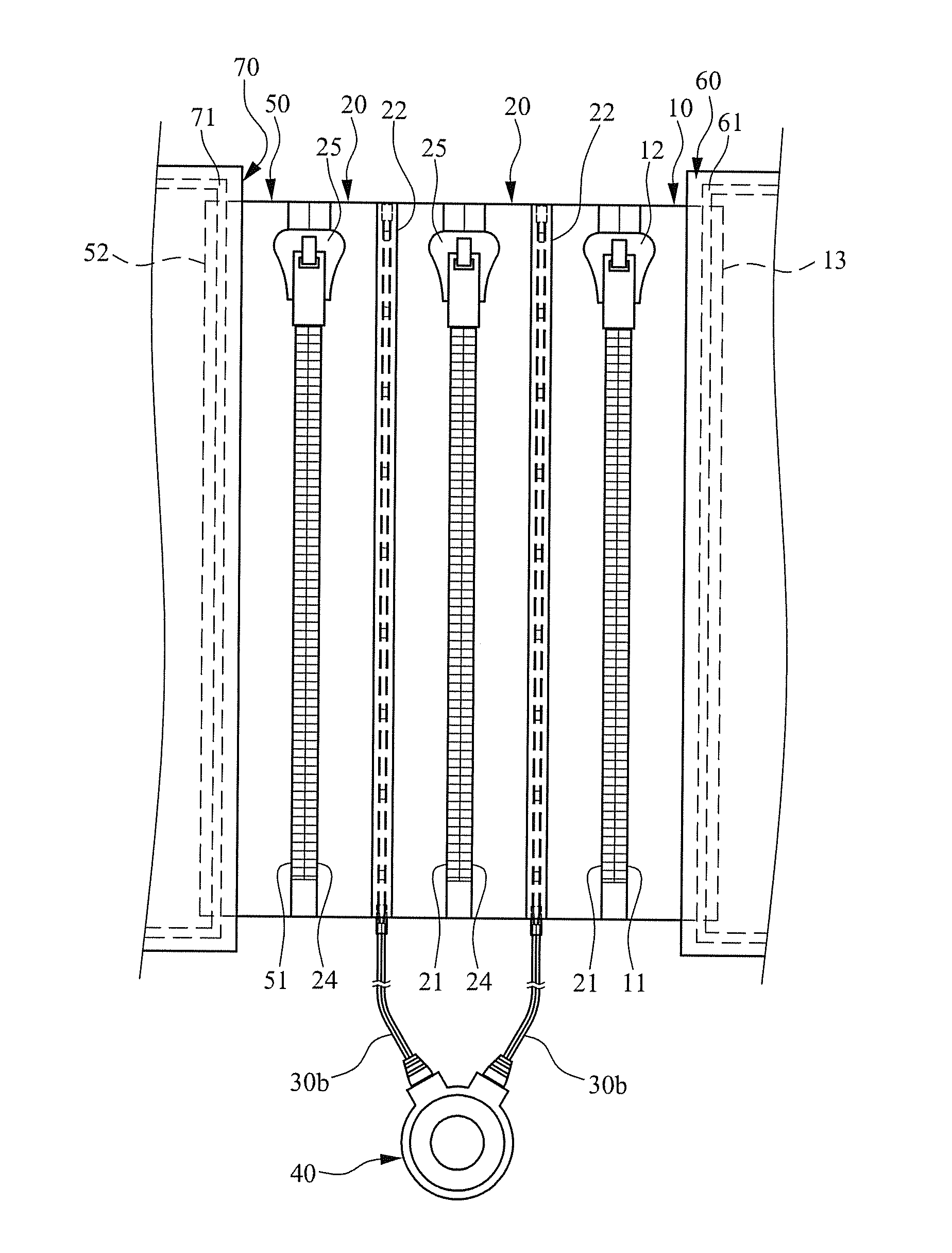
[0027]Referring to FIGS. 7 and 8, a removable zipper constructed in accordance with a second embodiment of the present invention is show, which is different from the above discussed first embodiment in that in this embodiment, the second tape 20 has an opposite edge to which a third tape 50 is connected. A second counterpart tooth row 24 and a second slider 25 are mounted to said opposite edge of the second tape 20 and the second slider 25 is movably coupled to and reciprocally slidable along the second counterpart tooth row 24. The second counterpart tooth row 24 has two opposite ends to which stops 24a, 24b are respectively mounted to prevent the second slider 25 from undesired separation. The third tape 50 comprises a third tooth row 51 formed along an edge thereof. The third tooth row 51 has an end to which a stop 51a, functioning to prevent undesired separation is provided and an opposite end to which an insertion pin 51b is mounted for engagement with the stop 24b of the secon...


PUM


Abstract

The present invention relates to a light bar-combined removable zipper, which includes a first tape, a second tape, a light bar, and a controller. The second tape has an edge joinable to an edge of the first tape to constitute a removable zipper structure. The light bar is combined to the second tape. The controller is connected to the light bar to supply electrical power to and selectively activate / deactivate the lighting of the light bar.

Description

FIELD OF THE INVENTION[0001]The present invention relates to a removable zipper with a light bar combined therewith, and in particular to a light bar-combined removable zipper for use in articles such as clothing and accessories.BACKGROUND OF THE INVENTION[0002]A conventional zipper comprises a pair of woven tapes, a plurality of teeth, and a slider. The teeth are arranged along opposing edges of the two tapes to form mateable tooth rows. Stops are set at opposite ends of each tooth row. The tooth row of one of the tapes functions to guide a reciprocal sliding motion of the slider for combining or releasing the two tooth rows to form or break a closed chain of the zipper. Such an arrangement allows the conventional zippers to be applicable to wearable articles, such as clothes and trousers, to make the wearable articles readily put on / off by a user. Due to the potential marketability and sales of zippers, light-reflective zippers, which are particularly fit to nighttime use, are ava...

Claims


Application Information

Patent Timeline
IPC IPC(8): F21V1/06
CPCF21V33/0008
Inventor HUANG, HONG-HSUKANG, CHI-SHUSU, I-CHENPENG, JUNG-HSIANG
Owner KINGS METAL FIBER TECH
Why Eureka
Try Eureka