Energy recovery ventilation smoke evacuation

a technology of energy recovery ventilation and smoke evacuation, applied in ventilation systems, lighting and heating apparatuses, heating types, etc., can solve problems such as conflict and misoperation

Active Publication Date: 2013-09-26
AIR DISTRIBUTION TECH IP LLC
View PDF37 Cites 17 Cited by
  • Summary
  • Abstract
  • Description
  • Claims
  • Application Information

AI Technical Summary

Benefits of technology

[0004]A control system is provided that includes one or more smoke sensors, each configured to measure a level of smoke at a location within a building and to output a smoke level signal based at least in part upon the measured level of smoke, such as a smoke detector for a fire or security system. A controller receives the smoke level signals and controls the operation of one or more energy recovery ventilation systems in a first mode of operation to recover energy when the smoke level signal is below a predetermined value and in a second mode of operation to evacuate smoke when the smoke level signal is above the predetermined value.

Problems solved by technology

However, operation of such building exhaust fans is independent of other heating, ventilating and air conditioning system components, which can create conflicts and misoperation with such components.

Method used


Image

  • Energy recovery ventilation smoke evacuation
  • Energy recovery ventilation smoke evacuation
  • Energy recovery ventilation smoke evacuation

Examples


Embodiment Construction

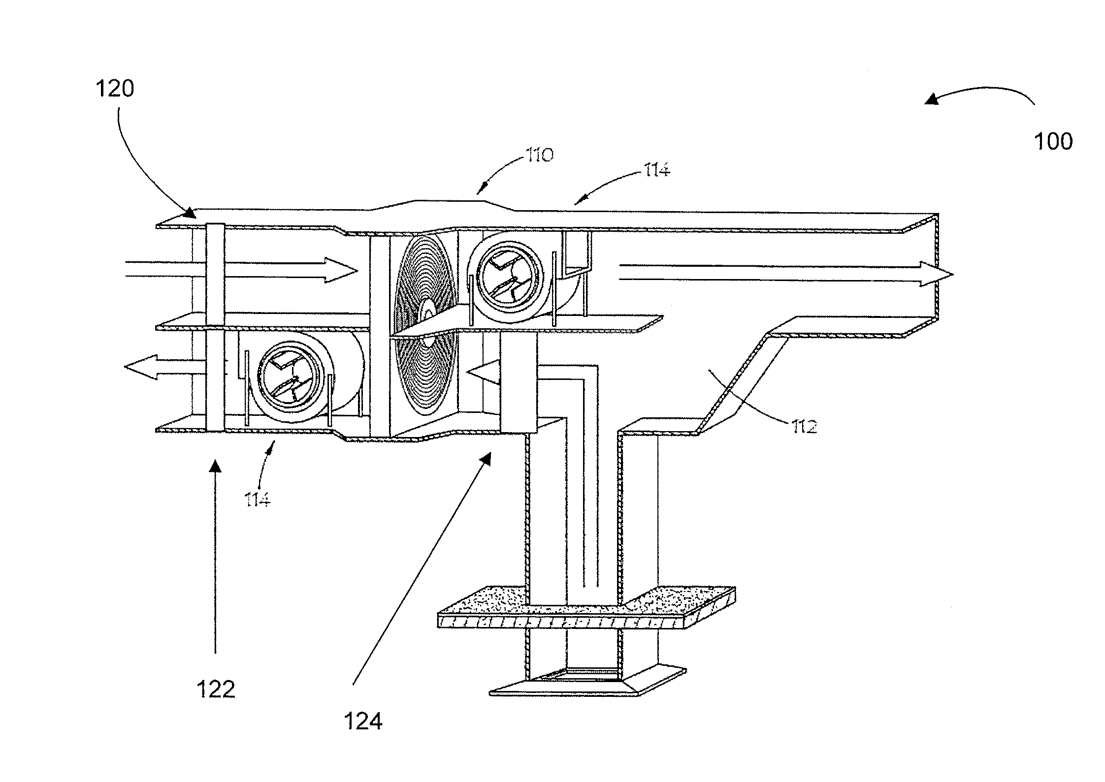
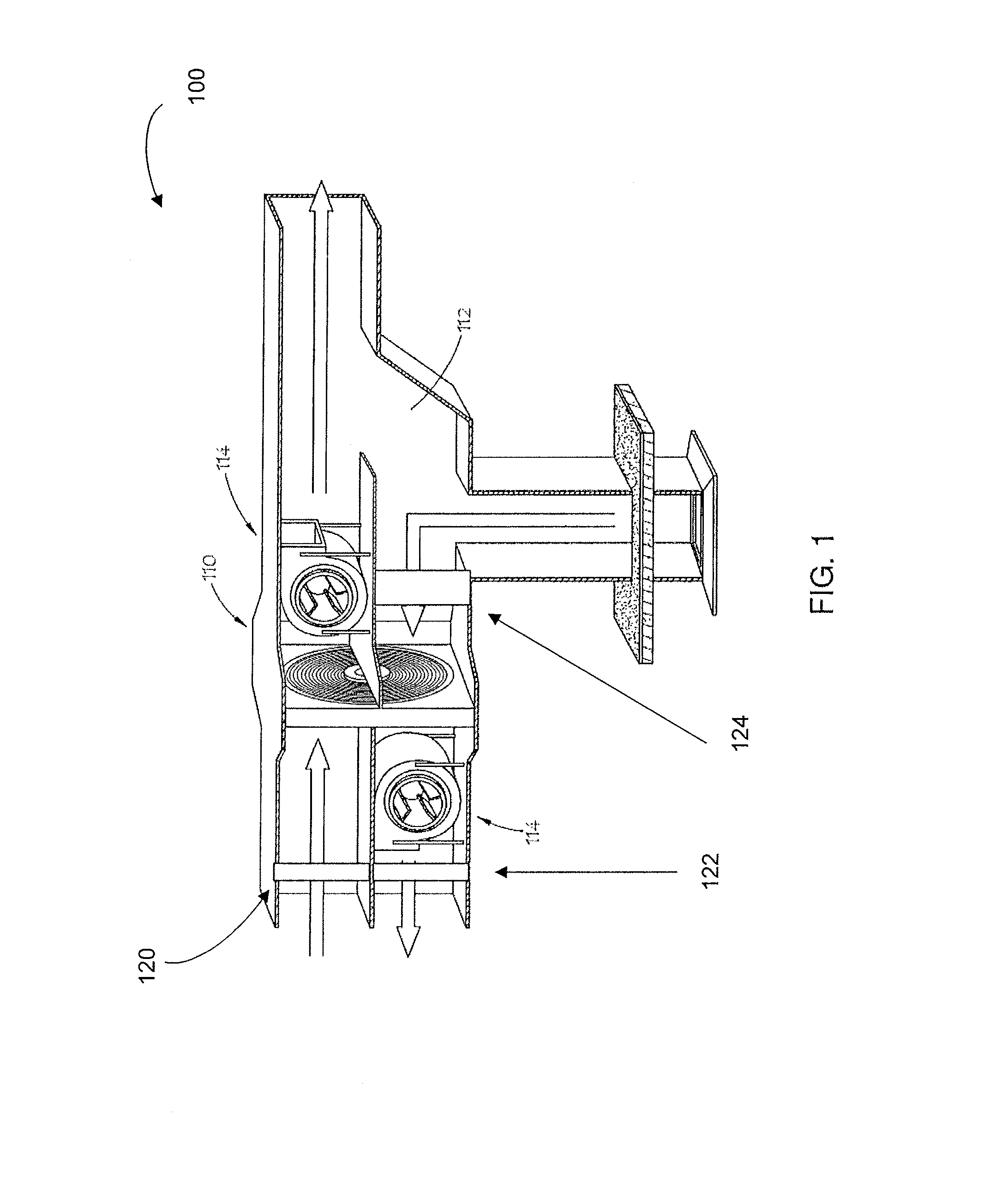
[0013]In the description that follows, like parts are marked throughout the specification and drawings with the same reference numerals. The drawing figures might not be to scale and certain components can be shown in generalized or schematic form and identified by commercial designations in the interest of clarity and conciseness.

[0014]The present disclosure is directed to systems and methods which control energy recovery ventilation (ERV) systems of buildings. ERV systems can be used to recover energy and lower utility expenses. In one exemplary embodiment, energy recovery wheels rotate between the incoming outdoor air and the building exhaust air. As the wheel rotates, it transfers a percentage of the heat and moisture differential from one airstream to the other. In this manner, the outdoor air is pre-conditioned, which reduces the capacity and energy needed from the mechanical heating, ventilating and air conditioning (HVAC) system to process the outdoor air. According to certa...


PUM


Abstract

A control system, comprising one or more smoke sensors, each configured to measure a level of smoke at a location within a building and to output a smoke level signal based at least in part upon the measured level of smoke. A controller configured to receive the smoke level signals and to control an operation of one or more energy recovery ventilation systems in a first mode of operation to recover energy when the smoke level signal is below a predetermined value and in a second mode of operation to evacuate smoke when the smoke level signal is above the predetermined value.

Description

RELATED APPLICATIONS[0001]The present application claims benefit of U.S. Provisional patent application No. 61 / 612,997, filed Mar. 20, 2012, entitled “ENERGY RECOVERY VENTILATION SMOKE EVACUATION,” which is hereby incorporated by reference for all purposes as if set forth herein.TECHNICAL FIELD[0002]The present disclosure relates generally to air handling systems for buildings, and more particularly to energy recovery ventilation systems, and specifically to methods and systems for smoke evacuation.BACKGROUND OF THE INVENTION[0003]Building exhaust fans are used to exhaust air from a building, such as when there is smoke or carbon dioxide. However, operation of such building exhaust fans is independent of other heating, ventilating and air conditioning system components, which can create conflicts and misoperation with such components.SUMMARY OF THE INVENTION[0004]A control system is provided that includes one or more smoke sensors, each configured to measure a level of smoke at a lo...

Claims


Application Information

Patent Timeline
Patent Type & Authority Applications(United States)
IPC IPC(8): F24F11/00F24F7/08
CPCF24F11/0017F24F7/08Y02B30/78F24F2011/0024F24F2203/104F24F11/0076F24F11/30F24F2110/50F24F2110/62F24F11/70Y02B30/70F24F11/34F24F11/33F24F11/35
Inventor WILEY, JOSIAHLONGMAN, MICHAEL G.
Owner AIR DISTRIBUTION TECH IP LLC
Why Eureka
Try Eureka