Steel fibre for reinforcing concrete or mortar having an anchorage end with at least three straight sections

Active Publication Date: 2013-10-03
NV BEKAERT SA
View PDF4 Cites 13 Cited by
  • Summary
  • Abstract
  • Description
  • Claims
  • Application Information

AI Technical Summary

Benefits of technology

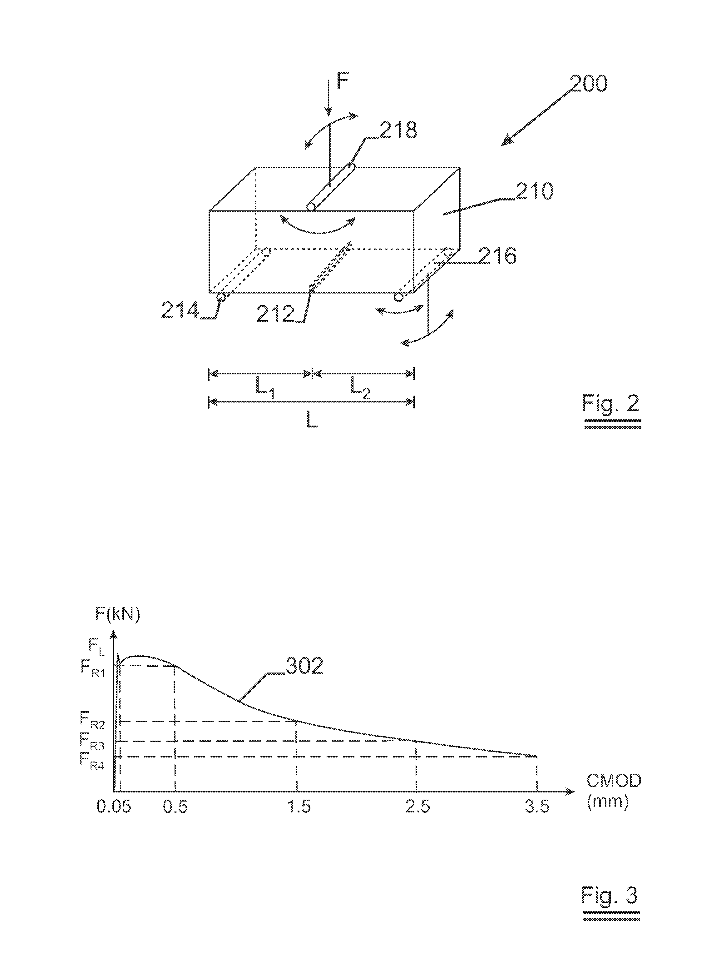
[0060]For this invention the material properties used for evaluating the performance in ULS and SLS of steel fibre reinforce concrete is the residual flexural tensile strength fR,i. The residual flexural tensile strength is derived from the load at a predetermined crack mouth opening displacement (CMOD) or midspan deflection (δR).
[0061]The residual flexural tensile strengths are determined by means of a three point bending test according to European Standard EN 14651 (described further in this application).
[0062]The residual flexural tensile strength fR,1 is determined at CMOD1=0.5 mm (δR,1=0.46 mm), the residual flexural tensile strength fR,2 is determined at CMOD2=1.5 mm (δR,2=1.32 mm), the residu

Problems solved by technology

Concrete is a brittle material having low tensile strength and low strain capacity.
However, the disadvantage of currently known prior art fibres is the relatively low performance at ultimate limit state (ULS) when low or moderate dosages of fibres are used.
These high dosages do not facilitate the mixing

Method used


Image

  • Steel fibre for reinforcing concrete or mortar having an anchorage end with at least three straight sections
  • Steel fibre for reinforcing concrete or mortar having an anchorage end with at least three straight sections
  • Steel fibre for reinforcing concrete or mortar having an anchorage end with at least three straight sections

Examples


Embodiment Construction

[0117]The present invention will be described with respect to particular embodiments and with reference to certain drawings but the invention is not limited thereto but only by the claims. The drawings described are only schematic and are non-limiting. In the drawings, the size of some of the elements may be exaggerated and not drawn on scale for illustrative purposes. The dimensions and the relative dimensions do not correspond to actual reductions to practice of the invention.

[0118]The following terms are provided solely to aid in the understanding of the inventions.

[0119]Maximum load capacity (Fm): the greatest load which the steel fibre withstands during a tensile test;

[0120]Elongation a maximum load (%): increase in the gauge length of the steel fibre at maximum force, expressed as a percentage of the original gauge length;

[0121]Elongation at fracture (%): increase in the gauge length at the moment of fracture expressed as a percentage of the original gauge length;

[0122]Tensile...


PUM

PropertyMeasurementUnit
Angleaaaaaaaaaa
Angleaaaaaaaaaa
Angleaaaaaaaaaa

Abstract

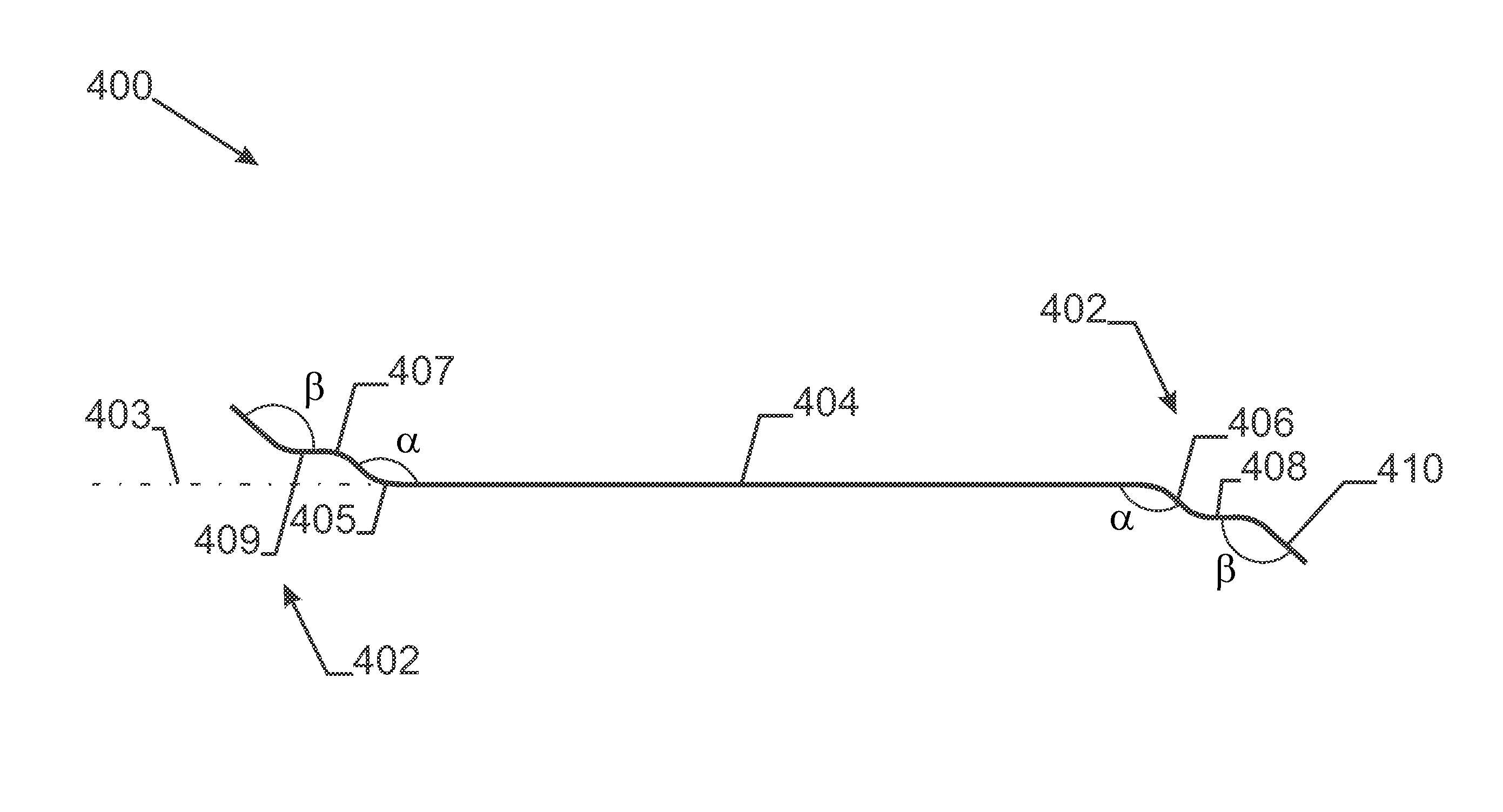
A steel fibre for reinforcing concrete or mortar has a middle portion and an anchorage end at one or both ends of the middle portion. The middle portion has a main axis. The anchorage end comprises at least a first straight section, a first bent section, a second straight section, a second bent section and a third straight section. The first straight section and the third straight section are bending away from the main axis of the middle portion in the same direction. The second straight section is substantially parallel with the main axis of said middle portion.

Description

TECHNICAL FIELD [0001]The invention relates to steel fibres for reinforcing concrete or mortar provided with anchorage ends allowing to obtain a good anchorage when embedded in concrete or mortar. The steel fibres according to the present invention have at least one anchorage end with at least 3 straight sections. The steel fibres according to the present invention show a good performance at service-ability limit state (SLS) and at ultimate limit state (ULS) when embedded in concrete or mortar. The invention further relates to concrete or mortar structures comprising such steel fibres.BACKGROUND ART [0002]Concrete is a brittle material having low tensile strength and low strain capacity. To improve properties of concrete like tensile strength and strain capacity, fibre reinforced concrete and more particularly metallic fibre reinforced concrete has been developed.[0003]It is known in the art that the properties of the fibres like fibre concentration, fibre geometry and fibre aspect ...

Claims


Application Information

Patent Timeline
IPC IPC(8): E04C5/01
CPCY10T428/1241E04C5/012Y10T29/49801Y10T428/2913Y10T428/249935E04C5/01E04C5/07C04B20/0048
Inventor LAMBRECHTS, ANNVAN HAEKE, MARTIN
Owner NV BEKAERT SA
Why Eureka
Try Eureka