[0016]With the method and device in accordance with the present invention,
oxygen is removed from the pouch before the filling step and the pouch is again degassed immediately prior to filling. Therefore, the inclusion of air into the content or occurrence of bubbles during filling is reduced and the packaging is performed with a high deoxidation ratio and can maintain high quality of the content, in particular such that can easily deteriorate under the effect of
oxygen, these deoxidation ratio and maintained quality being superior to those attained with the conventional process in which gas replacement is performed after the pouch is directly filled with the content.
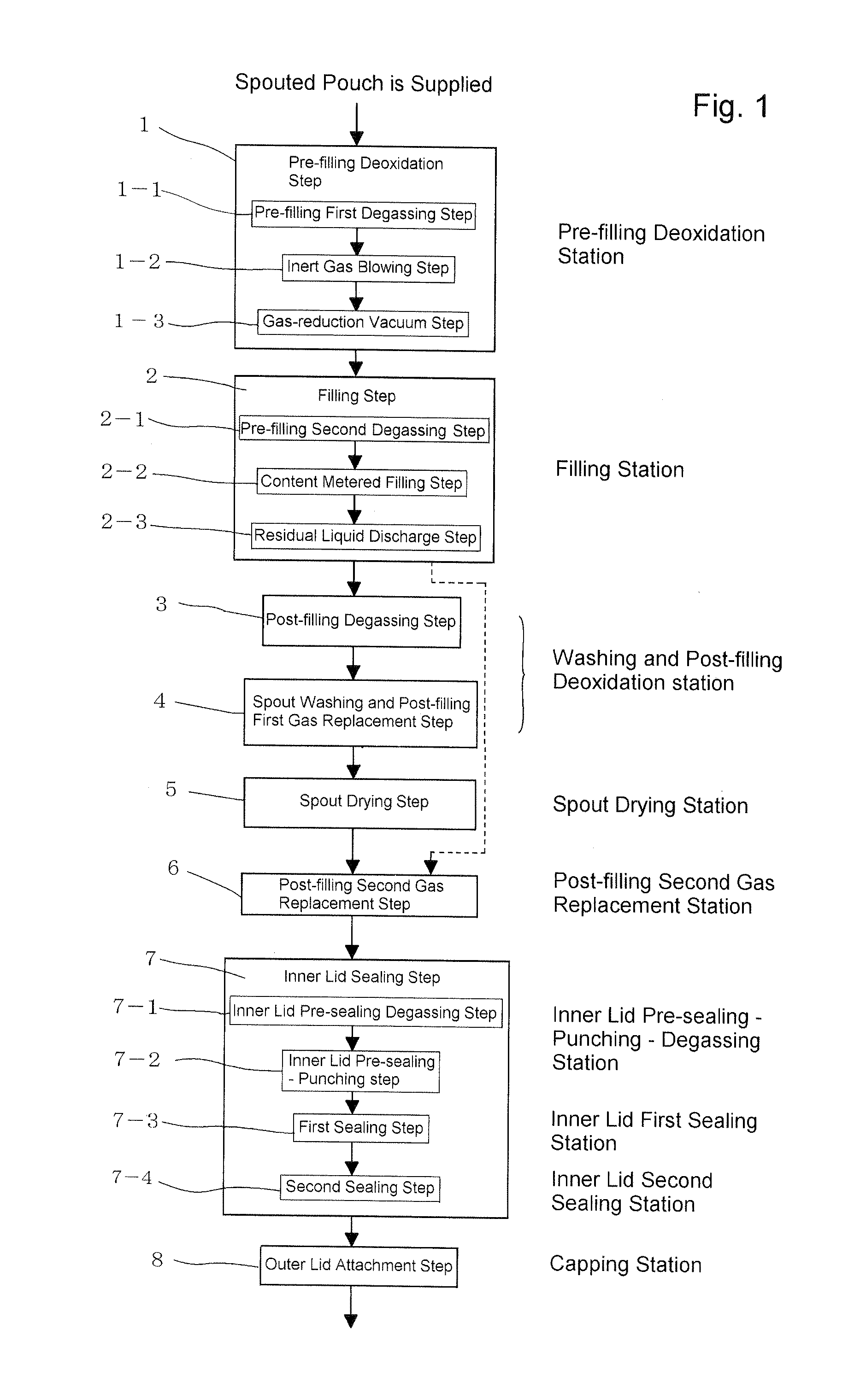
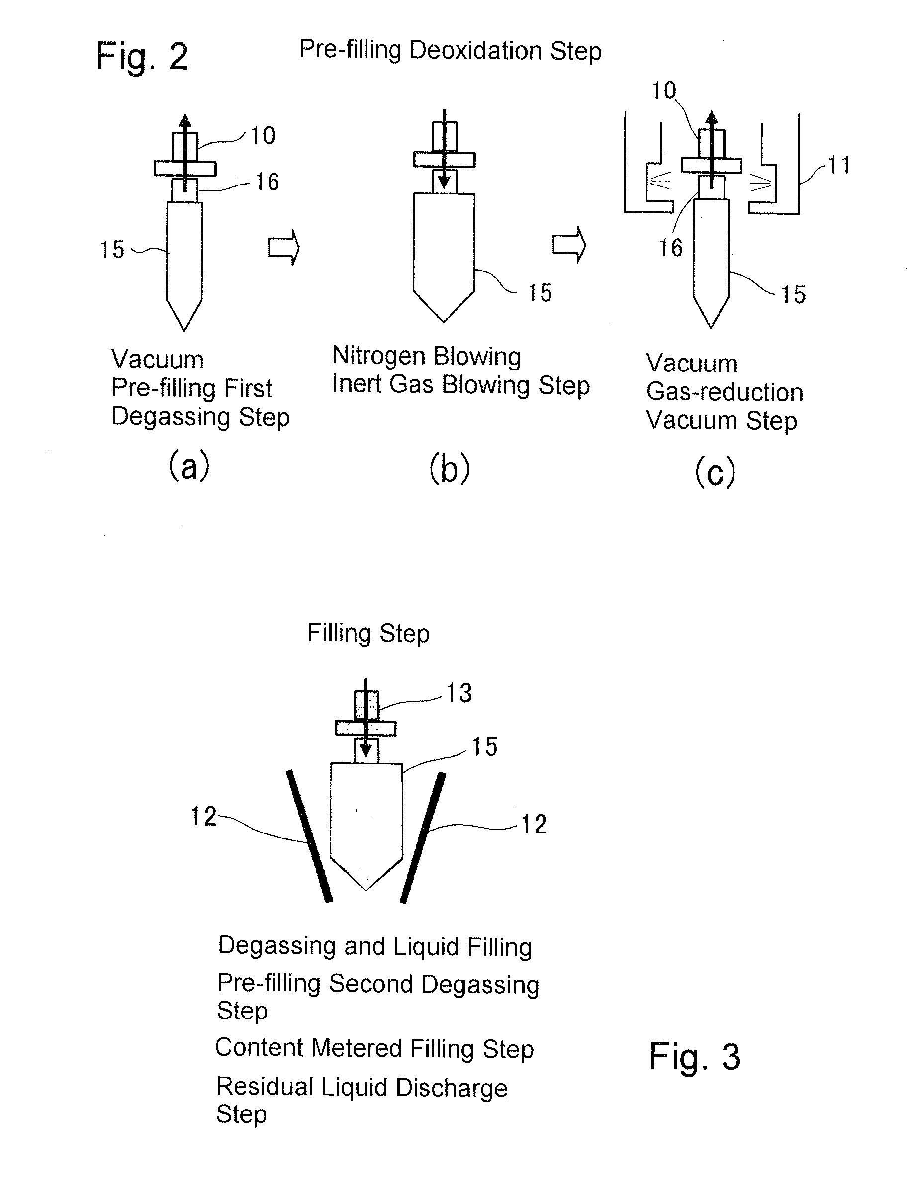
[0017]According to the invention as set forth in claim 2 and claim 9, the pre-filling deoxidation step includes a vacuum step, an
inert gas blowing step, and a gas-reduction vacuum step. Therefore, a sufficient amount of
inert gas can be blown into the pouch, without affecting the subsequent pre-filling degassing step, the pre-filling deoxidation ratio is high, and a portion that becomes bubbles after filling can be efficiently replaced with
inert gas. Furthermore, because
oxygen can be removed from the pouch before the filling step, the inclusion of air into the content or occurrence of bubbles during filling is reduced and the packaging is performed with a high deoxidation ratio and can maintain high quality of the content, in particular such that can easily deteriorate under the effect of oxygen, these deoxidation ratio and maintained quality being superior to those attained with the conventional process in which gas replacement is performed after the pouch is directly filled with the content.
[0018]Furthermore, according to the invention as set forth in claim 3 and claim 9, the penetration of external air into the pouch, in particular after the pre-filling gas replacement, can be prevented and a transition to the content filling step can be made, while maintaining a high deoxidation ratio.
[0019]According to the invention as in claim 4 and claim 10, bubbles and gas that are present after filling are discharged from the container. Therefore, gas replacement that is subsequently performed can be performed effectively.
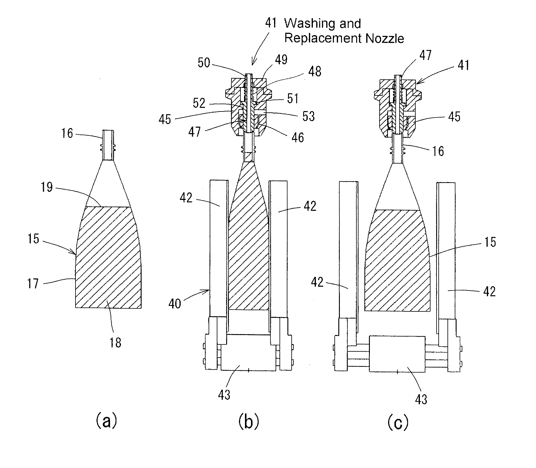
[0020]According to the invention as set forth in claims 5, 12, and 13, the residual liquid contained in the
nozzle after the metered filling step can be filled into the pouch, without generating bubbles, and filling of easily foamable content is effectively performed. According to the invention as set forth in claim 6, because the pouch is pressurized from the outside and degassed immediately before the content filling step, the degassing time can be shortened, the content can be filled in a state in which the amount of oxygen inside the pouch is reduced, without hindering the increase in
line rate, oxygen is prevented from dissolving in the content during filling, the occurrence of bubbles in the head space is prevented, the amount of oxygen present in a dissolved state in the content can be reduced, the deoxidation effect inside the pouch is increased, and content quality preservation can be improved.
[0021]According to the invention as set forth in claims 7 and 15, the degassing step and washing and gas replacement step can be effectively performed in the same
station and are performed in the
station following the filling
station. Therefore, spilling of the content caused by impacts during conveying is reduced even without expanding the pouch to lower the level of liquid content in the filling station, and even if spilling occurs, it causes no problems because it occurs before the pouch is washed.

