

Aircraft interior configuration
- Summary
- Abstract
- Description
- Claims
- Application Information
AI Technical Summary
Benefits of technology
Problems solved by technology
Method used
Image

Examples
first embodiment
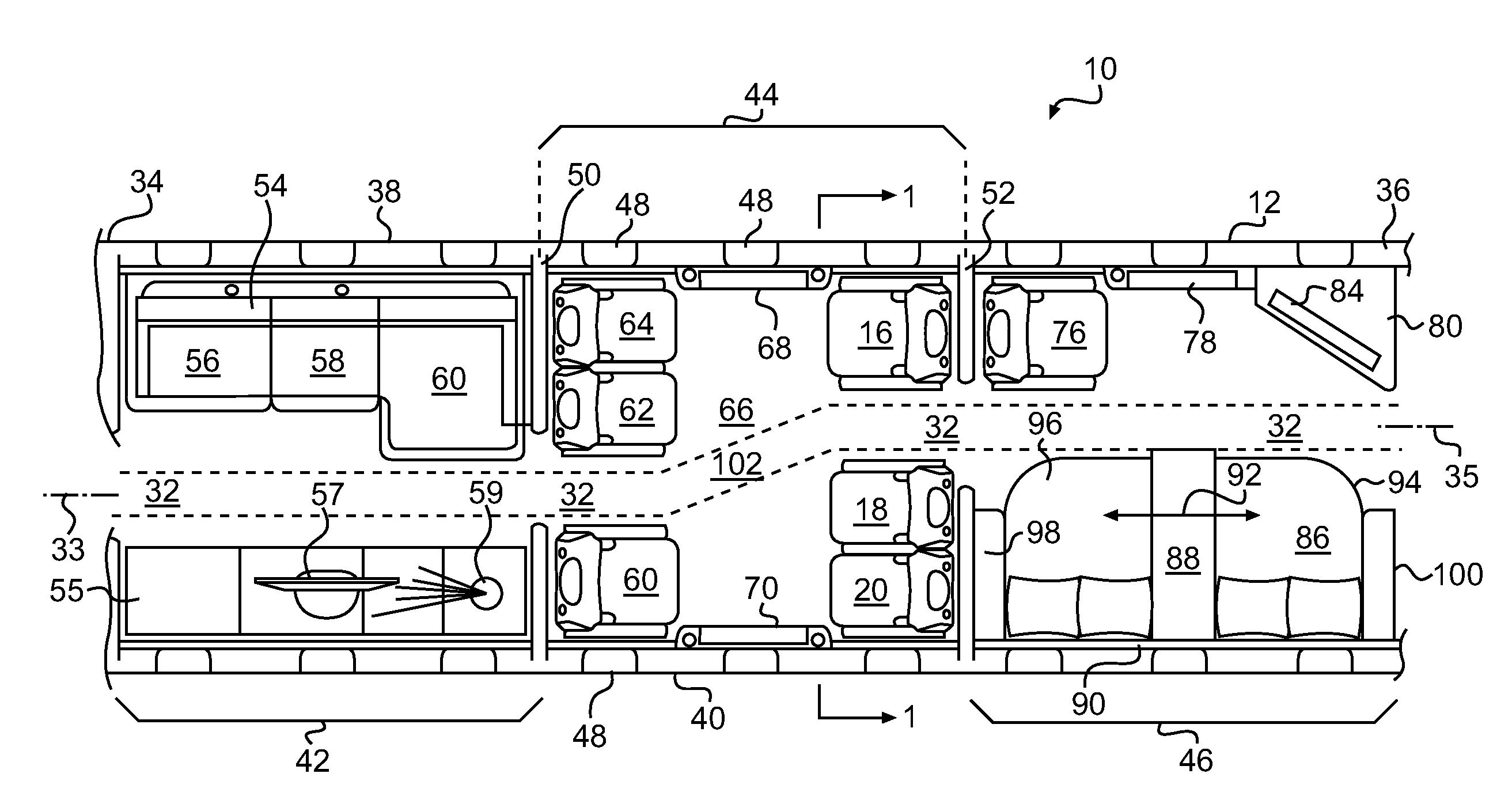
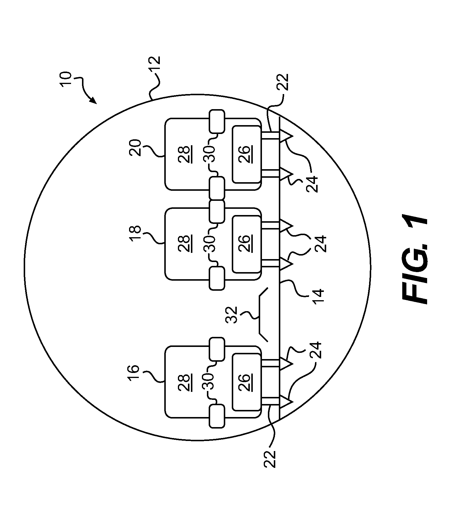
[0056]FIG. 1 is a cross-sectional illustration of an aircraft fuselage 10, which is taken along line I-I in FIG. 3. FIG. 1 provides a cross-section of the fuselage 10 that is consistent with the present invention. The cross-section also is applicable to other embodiments, as discussed below.
[0057]While a circular cross-section has been selected for the fuselage 10 depicted in FIG. 1, it is rioted that the cross-sectional shape of the fuselage 10 is not critical to operation any embodiment of the present invention. It is contemplated, for example, that the fuselage 10 alternatively may present a square or oval configuration, among others. In other words, the fuselage 10 may take any shape without departing from the scope of the present invention. For ease of illustration, a circular cross-section for the fuselage 10 has been selected for the various embodiments of the invention that are depicted herein.
[0058]Additionally, it is noted that the size of the fuselage 10 is not critical t...
second embodiment
[0115]As illustrated in FIG. 6, the conference table 208 is intended to present a variation of the table tops 72, 74 that are illustrated in FIG. 4. In this embodiment, the table tops 72, 74 are connected to one another via an insert or leaf 214.
[0116]As should be apparent from FIG. 6, to create the conference table 208, the table tops 72, 74 are first unfolded from their respective cabinets 68, 70. Subsequently, the insert or leaf 214 is positioned between the ends of the table tops 72, 74, thereby establishing a continuous conference table 208 that extends from one side of the fuselage 10 to the other.
third embodiment
[0117]FIG. 7 illustrates a conference table 210. In this illustration, the conference table 210 includes three sections that are supported by two pedestal legs 216, 218. Specifically, the pedestal leg 216 supports a first trapezoidal table top 220. The pedestal leg 218 supports a second trapezoidal table top 222. The first and second trapezoidal table tops 220, 222 are not intended to be stowed. Instead, the table tops 220, 222 are permanently deployed. As should be apparent, the table tops 220, 222 are intended to be placed in the central area 66 of the second compartment 44, between the seats 16, 18, 20, 60, 62, 64.
[0118]So that the table tops 220, 222 do not interfere with a passenger's ability to access one of the seats 16, 18, 20, 60, 62, 64 adjacent thereto, the trapezoidal table tops 220, 222 are provided with collapsible sections 224, 226, 228, 230.
[0119]As illustrated in FIG. 7, the trapezoidal table top 220 includes a central section 232 that is supported on the pedestal l...
PUM
 Abstract
Description
Claims
Application Information