Bumper structure

Active Publication Date: 2013-10-03
HONDA MOTOR CO LTD
View PDF17 Cites 10 Cited by
  • Summary
  • Abstract
  • Description
  • Claims
  • Application Information

AI Technical Summary

Benefits of technology

This patent describes a bumper structure that can prevent underride and absorb collisions when vehicles with different heights collide with each other. The structure has an opening that allows for proper load distribution, suppressing underride and allowing for appropriate absorption of the collision load. The bumper absorber also has a recess that further reduces underride and provides uniform absorption of the collision load. Overall, this bumper structure appropriately distributes and absorbs collisions to protect vehicles and their occupants.

Problems solved by technology

However, in the case where the bumper structures described in Japanese Unexamined Patent Application Publication Nos. 2007-182162 and 2008-056081 are employed, when a vehicle collides with the other vehicle having a height greater than that of the vehicle, there will be an unsquashed portion of the impact absorption member of the vehicle sandwiched between the bumper of the other vehicle and the bumper beam of the vehicle.
When the underride occurs, the bumper structures may not be able to appropriately absorb a collision load.
However, there is a problem that since only a small portion of the impact absorption member is squashed, a load will not be distributed by the impact absorption member, and the collision load will concentrate in a limited area in the vicinity of the center of the bumper beam.
As a result, the collision load will not be appropriately absorbed.

Method used


Image

  • Bumper structure
  • Bumper structure
  • Bumper structure

Examples


first embodiment

[0034]the present disclosure will be described in detail with reference to FIGS. 1 to 7B. In the following description, like elements will be denoted by like reference numerals, and repeated descriptions will be avoided. Directions described in the present application are based on the front, rear, right, left, up, and down directions as viewed by the driver of a vehicle. A vehicle width direction is the same as the right-left direction.

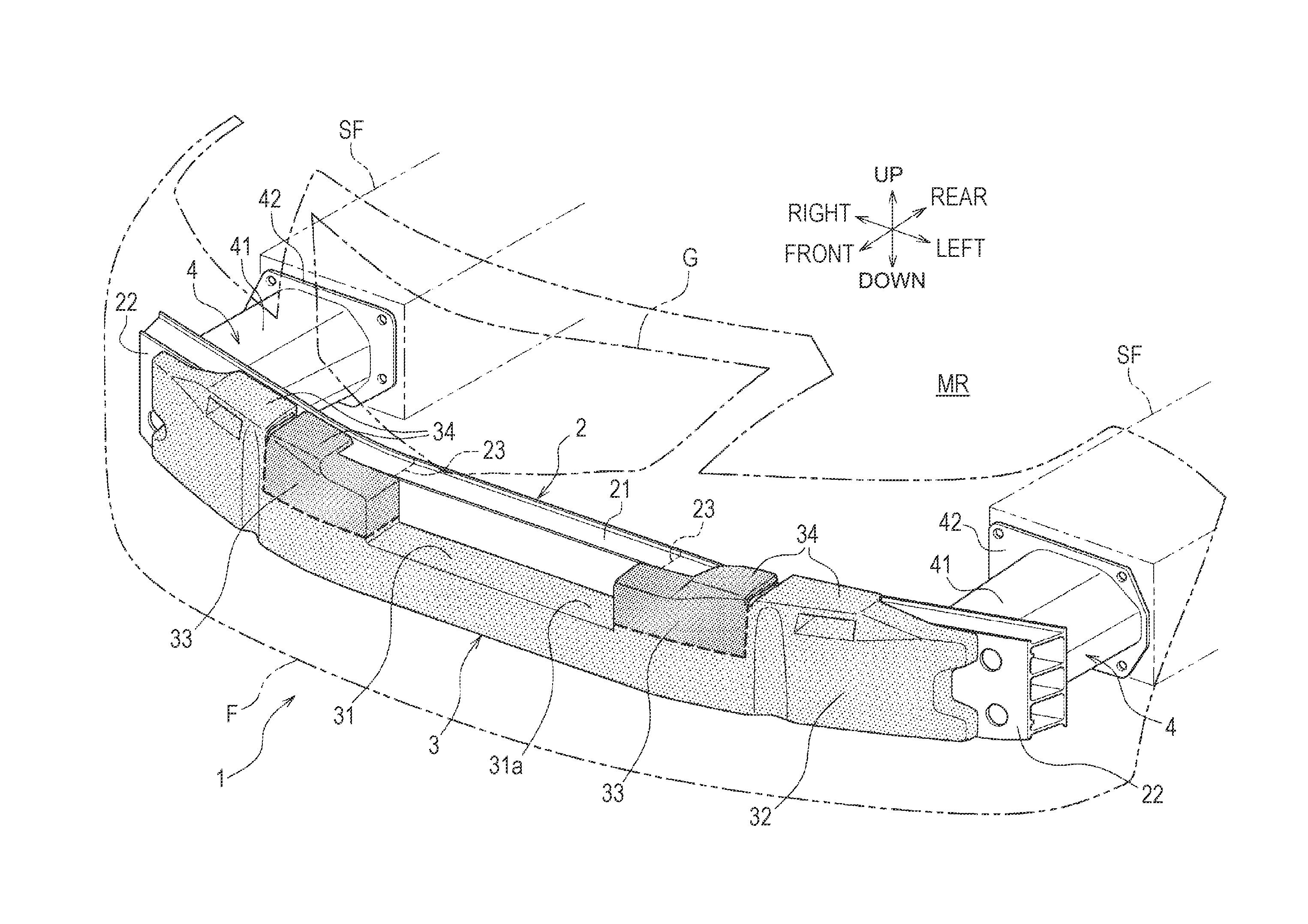
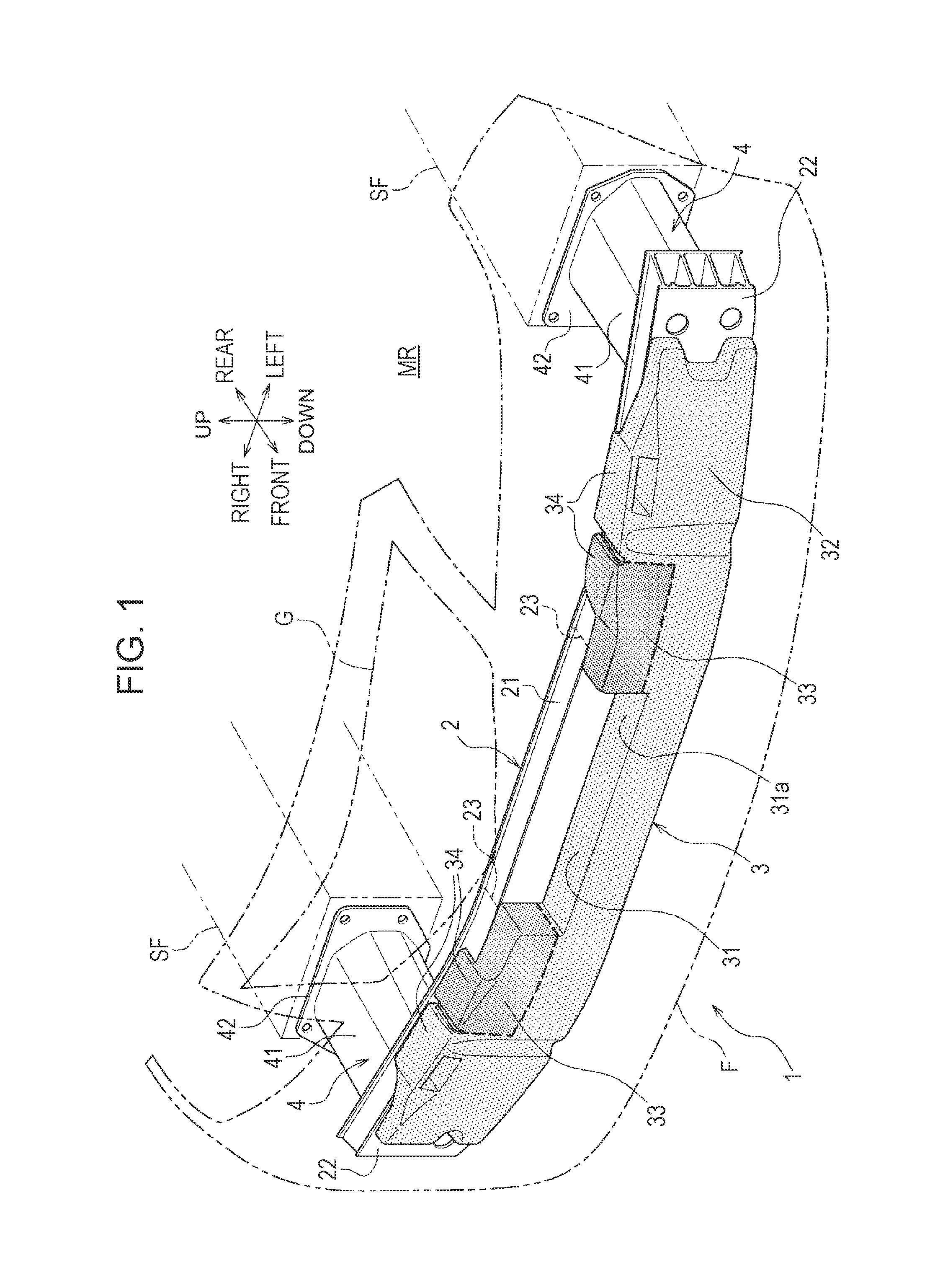
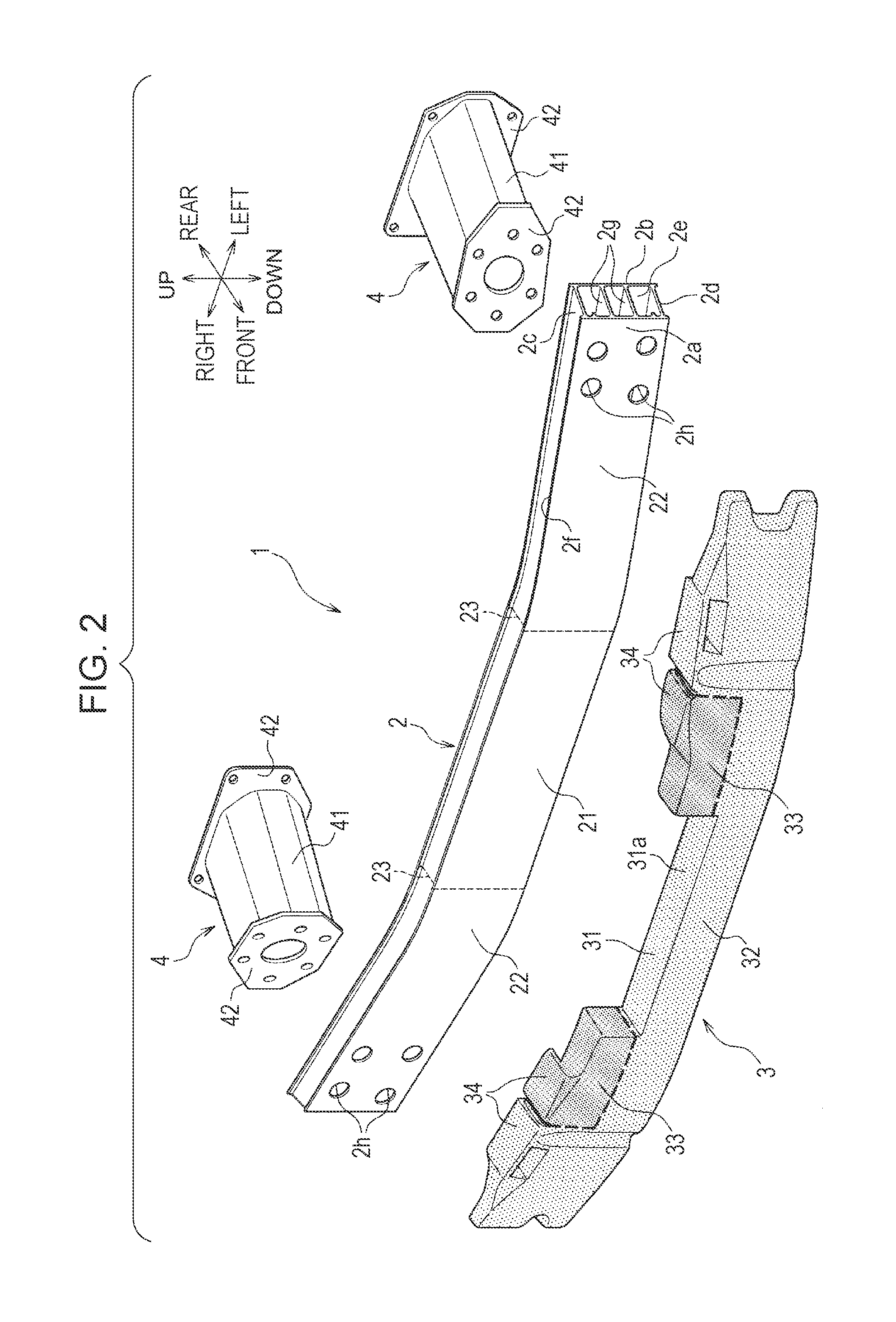
[0035]As shown in FIGS. 1 and 2, a bumper structure 1 according to the first embodiment is an apparatus that absorbs a collision load when the vehicle collides with another vehicle and is provided, for example, in a front end of the vehicle. The bumper structure 1 includes a bumper beam 2, a bumper absorber 3 that is provided on a front surface of the bumper beam 2, and a pair of bumper extensions 4 and 4 that are provided at both ends of the bumper beam 2 on the rear surface thereof.

[0036]A bumper face F and a front grill G are disposed in front of t...

second embodiment

[0061]As shown in FIGS. 8 to 10, the bumper structure 10 includes the bumper beam 2, a bumper absorber 7 that is provided on the front surface of the bumper beam 2, and a pair of bumper extensions (not shown).

[0062]The major difference between the bumper structure 1 according to the above-described first embodiment and the bumper structure 10 according to the second embodiment is that the bumper absorber 7 includes a recess 71 in the vicinity of the center thereof in the up-down direction of the vehicle.

[0063]The bumper absorber 7 includes the recess 71, which is a channel like structure and extends in the vehicle width direction, in the vicinity of the center thereof in the up-down direction of the vehicle. In other words, the bumper absorber 7 is divided into two portions (upper portion and lower portion) in the up-down direction by the recess 71 therebetween.

[0064]Because of this, when the vehicle collides with another vehicle having a height greater than that of the vehicle, th...


PUM


Abstract

A bumper structure includes a bumper beam that extends in a vehicle width direction and a bumper absorber that is provided along a front surface of the bumper beam and that has an opening in a top center portion of the bumper absorber in the vehicle width direction. The bumper beam includes a center portion that extends parallel to the vehicle width direction and a pair of oblique portions that obliquely extend backward and outward in the vehicle width direction from respective ends of the center portion. The bumper absorber includes a pair of load receiving portions outside the opening in the vehicle width direction, and the load receiving portions are arranged at positions corresponding to a pair of bent portions that are formed at boundaries between the center portion and the respective oblique portions.

Description

CROSS REFERENCES TO RELATED APPLICATIONS[0001]The present application claims priority under 35 U.S.C. §119 to Japanese Patent Application No. 2012-075954, filed Mar. 29, 2012, entitled “Bumper Structure.” The contents of this application are incorporated herein by reference in their entirety.TECHNICAL FIELD[0002]The present disclosure relates to bumper structures, and more specifically, to a bumper structure capable of suppressing the occurrence of underride collision and providing appropriate absorption of a collision load.BACKGROUND[0003]Bumper structures including a recessed opening formed in a top center portion in a vehicle width direction of an impact absorption member which is attached on a front surface of a front bumper beam have been disclosed.[0004]For example, in bumper structures disclosed (especially depicted with figures) in Japanese Unexamined Patent Application Publication Nos. 2007-182162 and 2008-056081, a protruding portion is formed in a top center portion of an...

Claims


Application Information

Patent Timeline
IPC IPC(8): B60R19/26
CPCB60R19/26B60R2019/1873B60R19/18
Inventor EBARA, YOSHIAKIKATSUMATA, KOUSUKE
Owner HONDA MOTOR CO LTD
Why Eureka
Try Eureka