Patterned obscuration lines for electrochromic devices

a technology of electrochromic devices and obscuration lines, applied in non-linear optics, instruments, optical elements, etc., can solve the problems of insufficient disguise of conspicuous or recognized misalignment, difficult installation or repair of igus, and high cost, so as to minimize the visual or actual impact, minimize the width, and maximize the unobstructed viewing area

Inactive Publication Date: 2013-10-03
SAGE ELECTROCHROMICS
View PDF3 Cites 48 Cited by
  • Summary
  • Abstract
  • Description
  • Claims
  • Application Information

AI Technical Summary

Benefits of technology

[0007]To lessen the visual or actual impact of these often undesirable features, at least one side of an electrochromic device, such as an edge thereof, may include one or more obscuration patterns. An obscuration pattern desirably may be designed to disguise undesirable features along the visible edges of an electrochromic device and have a minimum width necessary to perform this function in order to maximize the unobstructed viewing area through an electrochromic device and to add the least amount of cost to the production of such devices.
[0008]In some arrangements, an obscuration pattern may be printed. In some arrangements, the pattern may be formed using screen-printing of inorganic or organic inks, such as but not limited to an ink based on reactive acrylates, that bond to a substrate, such as but not limited to glass, after a heat treatment, such as but not limited to curing by ultraviolet light or other known curing methods. In some arrangements, the reactive acrylates preferably may be dark or pigmented, which may act to obscure a view of undesirable features. In some arrangements, an obscuration pattern is prepared by digital printing of organic inks, inorganic inks, or mixtures thereof. Such digital printing may be used to automatically and accurately print patterns, which may have any color, onto the substrate. In some arrangements, a pattern in accordance with the present invention may be formed onto glass, for example tempered glass used for vehicle windshields. In some arrangements, a screen-printed pattern may be printed on any of a series of attachable substrates such as but not limited to float glass, electrochromic glass, or a thin film material. In such arrangements, the pattern on each of these individual substrates may have approximately the same dimensions, each having approximately the same pattern.

Problems solved by technology

Current IGUs often have printed busbars and have non-active or non-coloring areas near edges of visible viewing regions within such IGUs that are generally perceived to be aesthetically undesirable features.
Current edge obscuration however utilizes a straight solid line, i.e., “hard edge,” that cannot sufficiently disguise conspicuous or recognized misalignment.
Precise alignment of the IGUs by a contractor, such as a glazing contractor, working on the installation or repair of IGUs may be difficult and expensive.

Method used


Image

  • Patterned obscuration lines for electrochromic devices
  • Patterned obscuration lines for electrochromic devices
  • Patterned obscuration lines for electrochromic devices

Examples


Embodiment Construction

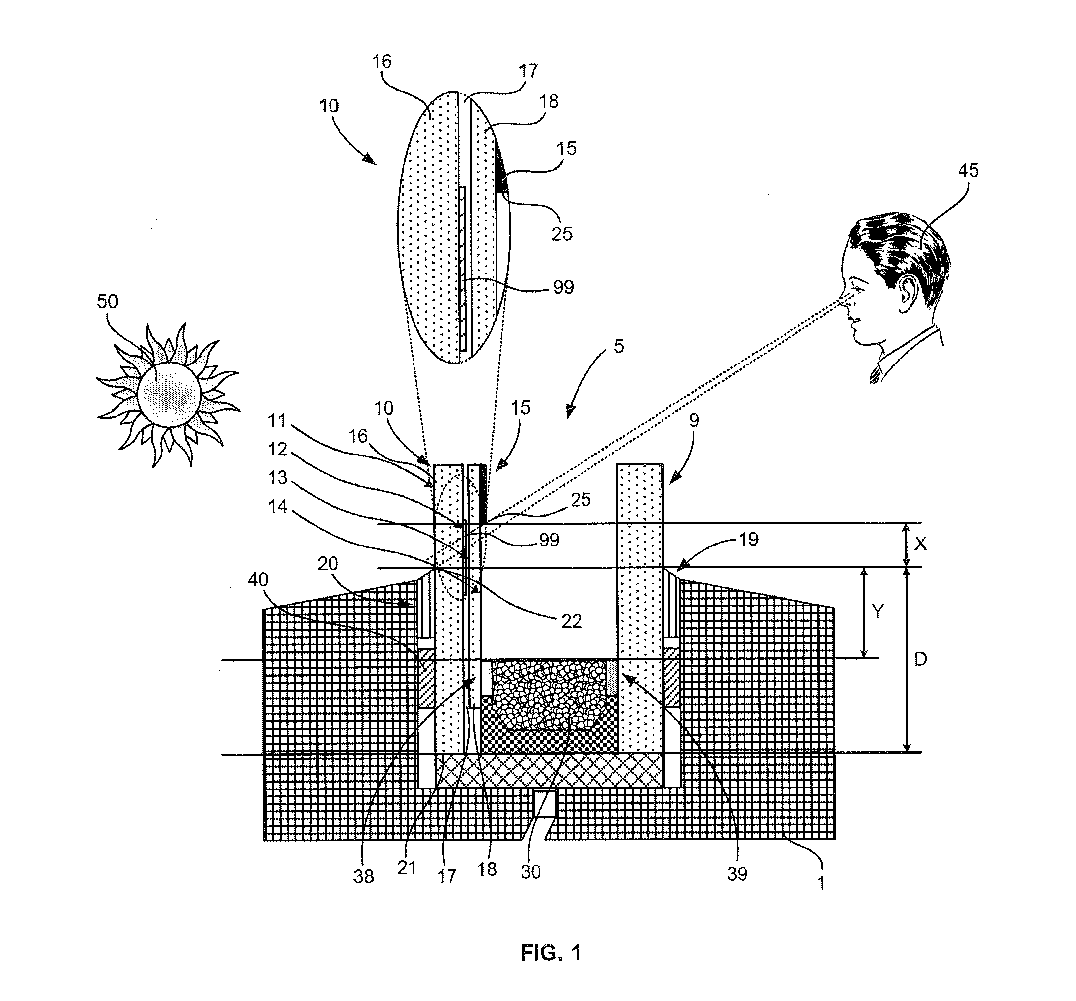
[0025]Referring to FIG. 1, in accordance with an embodiment, an electrochromic device may be an insulated glass unit (IGU) 5 having an inboard glass lite 9 and an outboard glass lite 10. As shown, the inboard glass lite 9 may be made clear float glass. As further shown, the outboard glass lite 10 may include an outer ply layer 16 between and defined by an exterior surface 11 and an interior surface 12, which may be made of clear float glass. The outboard glass lite 10 may include an inner ply layer 18 between and defined by an inner surface 13 and an inside surface 14. In some arrangements, the inner ply layer 18 may include a clear float glass. As shown in FIG. 1, the inside surface 14 of the inner ply layer 18 may be coated with an electrochromic coating 15, which may be various oxide thin films known to those of ordinary skill. The outboard glass lite 10 may include an interlayer 17 between the outer ply layer 16 and the inner ply layer 18, which may be a clear layer. Electrochro...


PUM

PropertyMeasurementUnit
thicknessaaaaaaaaaa
thicknessaaaaaaaaaa
thicknessaaaaaaaaaa

Abstract

An electrochromic device is provided. The device may be inserted within a frame. The device may include a substrate, an electrochromic coating, and a patterned layer. The electrochromic coating may overlie a portion of the substrate within a visible region of the substrate. The electrochromic coating may have an outer edge that is spaced from an outer boundary of the visible region of the substrate. The outer edge of the electrochromic coating and the outer boundary of the visible region may define a working region. The patterned layer may be deposited within the working region. The patterned layer may include a plurality of spaced apart shapes.

Description

CROSS-REFERENCE TO RELATED APPLICATIONS[0001]The present application claims the benefit of the filing date of U.S. Provisional Patent Application No. 61 / 619,719 filed Apr. 3, 2012, the disclosure of which is hereby incorporated herein by reference.FIELD OF THE INVENTION[0002]This invention relates to switchable or active technology glazing devices, and in particular, relates to the obscuration of such devices.BACKGROUND OF THE INVENTION[0003]Insulated glass units (IGUs) include opposing glass lite panels separated by a spacer along the edge in which the spacer and the glass sheets create a seal around a dead air space (or other gas, e.g., argon, nitrogen, krypton). A series of thin films, known as electrochromic glazings, are applied or deposited to one of the glass lite panels. Electrochromic glazings or coatings include electrochromic materials that are known to change their optical properties in response to the application of an electric potential which can create coloration or t...

Claims


Application Information

Patent Timeline
Patent Type & Authority Applications(United States)
IPC IPC(8): G02F1/157G02B1/10
CPCG02F1/157G02B1/10B32B17/10513C03C17/32C03C17/3405B32B17/10348B32B17/10266
Inventor PODBELSKI, LOUIS J.BUESING, OLESAVARY, JEAN-PHILIPPE
Owner SAGE ELECTROCHROMICS
Why Eureka
Try Eureka