
Eureka
For R&D, Eureka makes reading and utilizing patents & technical documents easy.
Eureka AIR
Designed for self-driven R&D workflows. Generate viable solutions, solve complex R&D challenges, empower your innovation with AI.

Eureka Materials
Designed for material experts only. Revolutionize your material R&D, from search, analyze, to developing new materials.

TechResearch
Generate reliable direction feasibility study reports for your R&D in just a few steps.

TechSeek
Discover and master advanced knowledge NOW. Basics, ideas, possibilities, all at once.

TechMind
As an expert in R&D Theories, TechMind can generates customized viable solutions instantly.

TechRisk
Analyze your overall solution with one click, know your potential R&D risks in advance.

TechMonitor
Get weekly tech updates, stay abreast of the latest tech innovations and key insights.
Optical apparatus and method of manufacturing the same
- Summary
- Abstract
- Description
- Claims
- Application Information
AI Technical Summary
Benefits of technology
Problems solved by technology
Method used
Image

Examples
embodiment 1
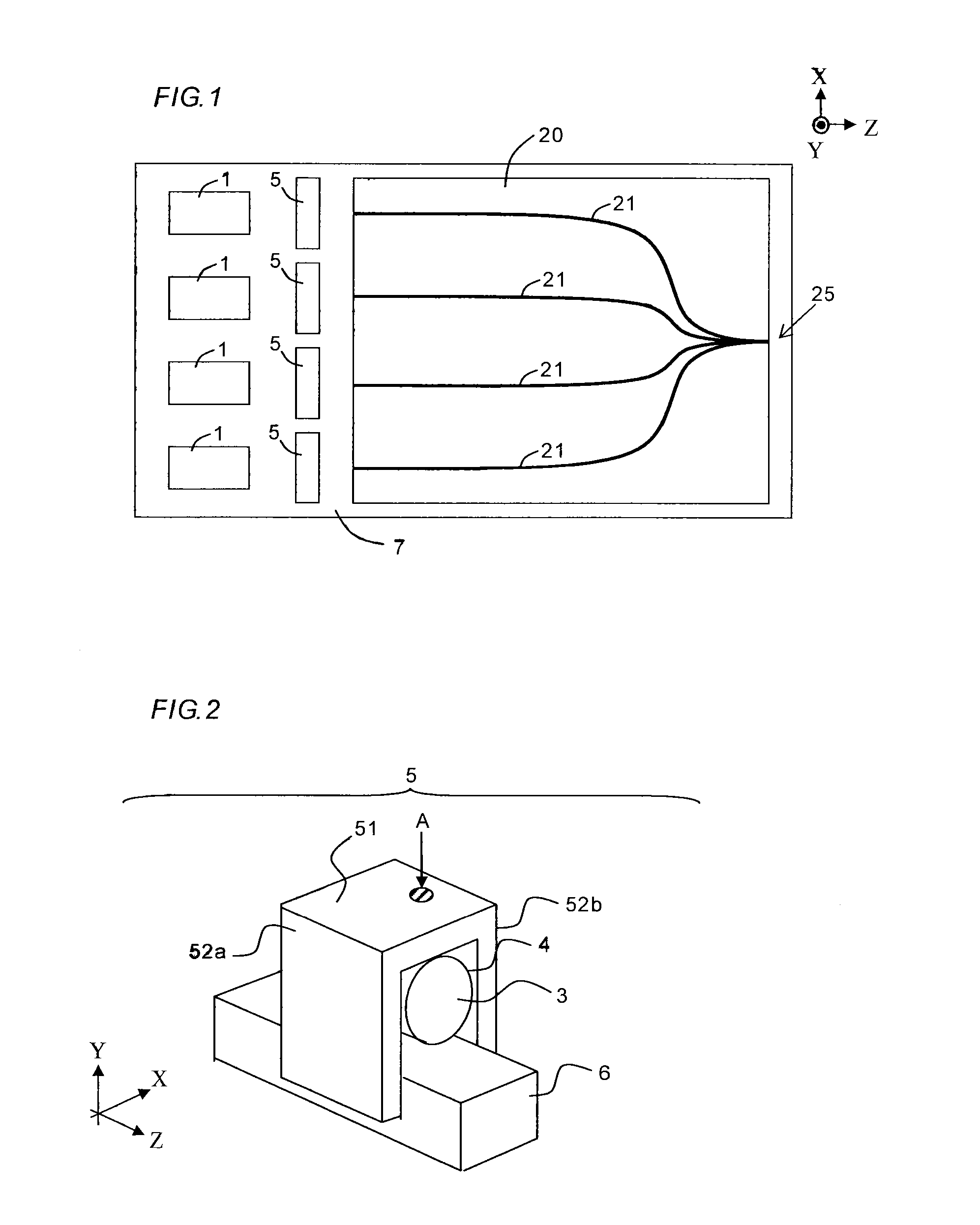
[0075]FIG. 1 is a configuration view showing an example of an optical transmitter to which the present disclosure can be applied. The optical transmitter has a function of simultaneously transmitting optical signals through a plurality of communication channels in a wavelength division multiplex mode or the like. Exemplified herein are four communication channels, while two, three, five or more communication channels can be configured in a similar manner.
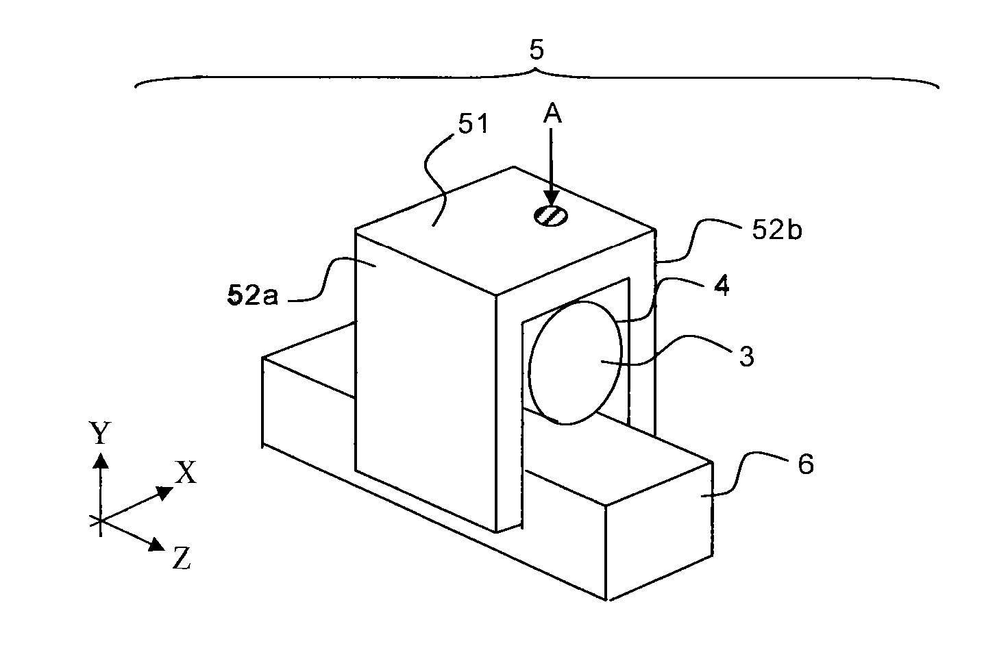
[0076]The optical transmitter includes four laser light sources 1, four lens holders 5, an optical multiplexer 20, and a substrate 7.
[0077]The laser light sources 1, which can be each configured of a semiconductor laser, a solid state laser or the like, generate light having center wavelengths different from each other in the wavelength division multiplex mode. The laser light sources 1 are bonded onto a submount (not shown) using a solder or an adhesive. The submount is fixed onto the substrate 7 using a solder or an adhesive. Such...
embodiment 2
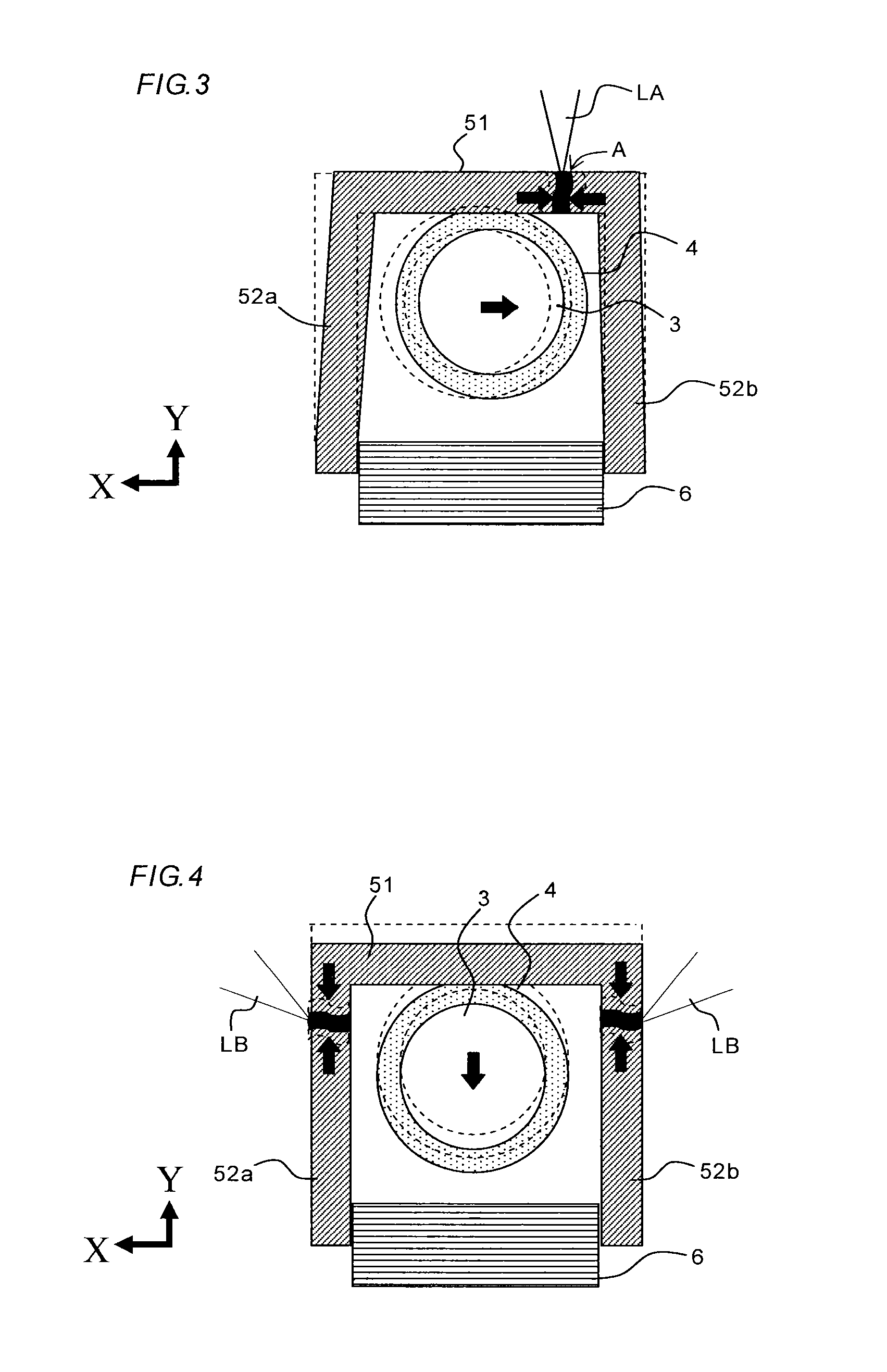
[0108]FIGS. 10A to 10C are configuration views according to Embodiment 2 of the present disclosure: FIG. 10A being a front view; FIG. 10B being a plan view; and FIG. 10C being a side view. A lens holder 5 includes a horizontal member 55 that extends along X direction, two vertical members 56a and 56b that extend along Y direction from both ends of the horizontal member 55, and has a shape of so-called gantry. A lens 3 is accommodated in a lens cylinder 4, which is held by the lens holder 5 to have the optical axis thereof in Z direction. The vertical members 56a and 56b are fixed to a holder carrier 6 that serves as a base member.
[0109]Each of the horizontal member 55 and the vertical members 56a and 56b is made of a material, such as stainless steel or silicon steel, that is plastically deformable by irradiation with laser light for processing, such as a YAG laser, and is preferably formed of a stainless steel plate having a thickness of 0.3 to 0.4 mm. Each of the lens cylinder 4 a...
embodiment 3
[0112]FIGS. 11A to 11A are configuration views according to Embodiment 3 of the present disclosure: FIG. 11A being a front view; FIG. 11B being a plan view; and FIG. 11C being a side view. A lens holder 5 is configured similarly to that shown in FIGS. 10A to 10C, but is different therefrom in that vertical members 56a and 56b are each provided at the center with an opening H and a lens cylinder 4 is partially inserted into the openings H.
[0113]This configuration can reduce the width (in X direction) of the lens holder 5, thereby downsizing it. Furthermore, the vertical members 56a and 56b can be each configured of slim pillars, thereby facilitating plastic deformation by laser spot irradiation. Similarly, by reducing the width of the horizontal member 55, plastic deformation can be easily realized by laser spot irradiation.
PUM
 Abstract
Description
Claims
Application Information
 - R&D Engineer
- R&D Manager
- IP Professional
- Industry Leading Data Capabilities
- Powerful AI technology
- Patent DNA Extraction
Browse by: Latest US Patents, China's latest patents, Technical Efficacy Thesaurus, Application Domain, Technology Topic, Popular Technical Reports.
© 2024 PatSnap. All rights reserved.Legal|Privacy policy|Modern Slavery Act Transparency Statement|Sitemap|About US| Contact US: help@patsnap.com