Swingable electronic candle

a swingable electronic and candle technology, applied in the field of electronic candles, can solve the problems of inflexible swingable heads, high simulation difficulty, and low degree of flexibility of swingable heads

Inactive Publication Date: 2013-10-03
SHANGHAI Q MALL
View PDF0 Cites 14 Cited by
  • Summary
  • Abstract
  • Description
  • Claims
  • Application Information

AI Technical Summary

Benefits of technology

[0015]Advantages of the invention are summarized below: the electronic candle provided by the invention is fully dynamic and has high degree of simulation. The candle end is flexible and swi

Problems solved by technology

However, most of the existing electronic candles only have a light-emitting body.
Some swingable ele

Method used


Image

  • Swingable electronic candle
  • Swingable electronic candle
  • Swingable electronic candle

Examples


Embodiment Construction

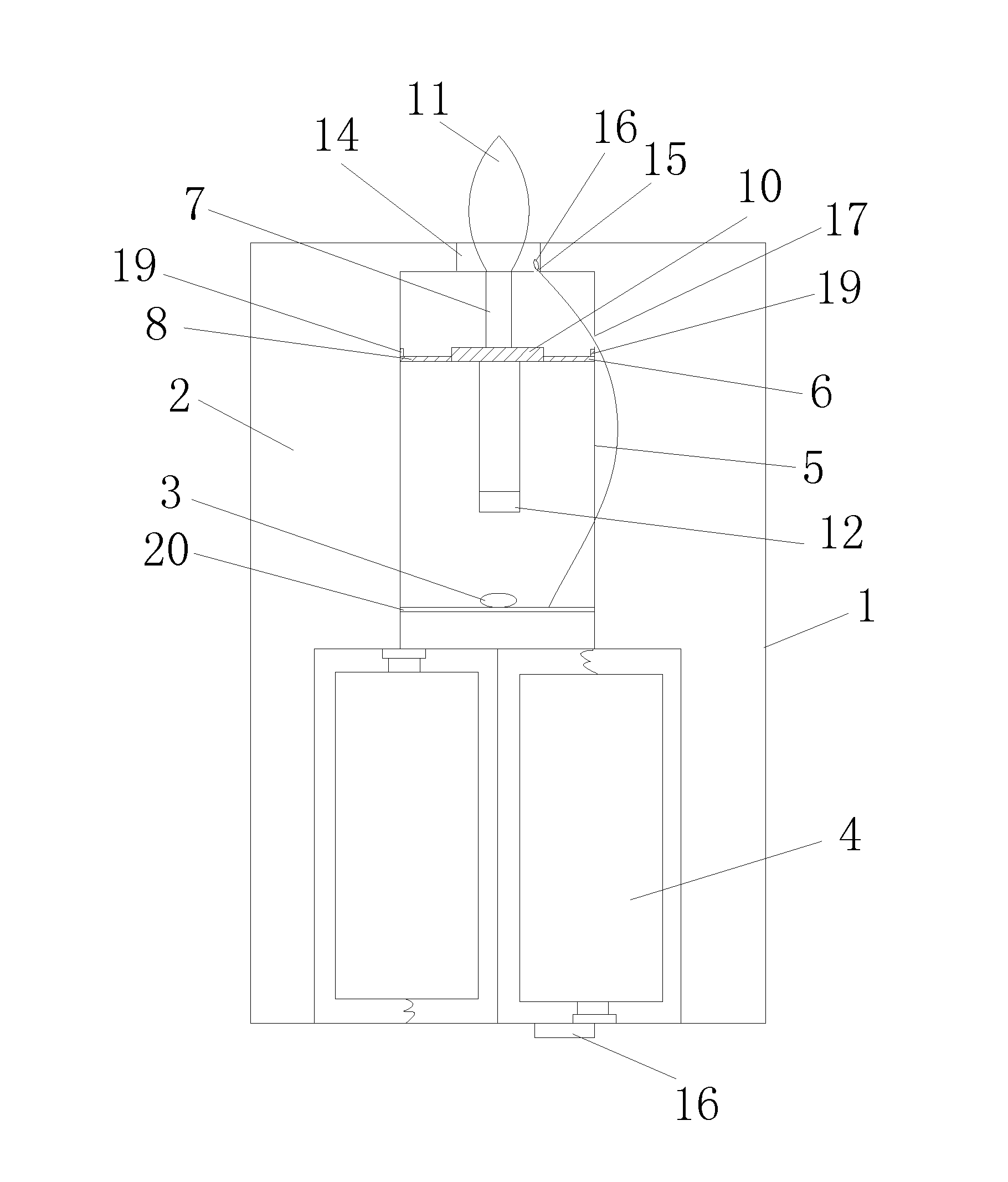
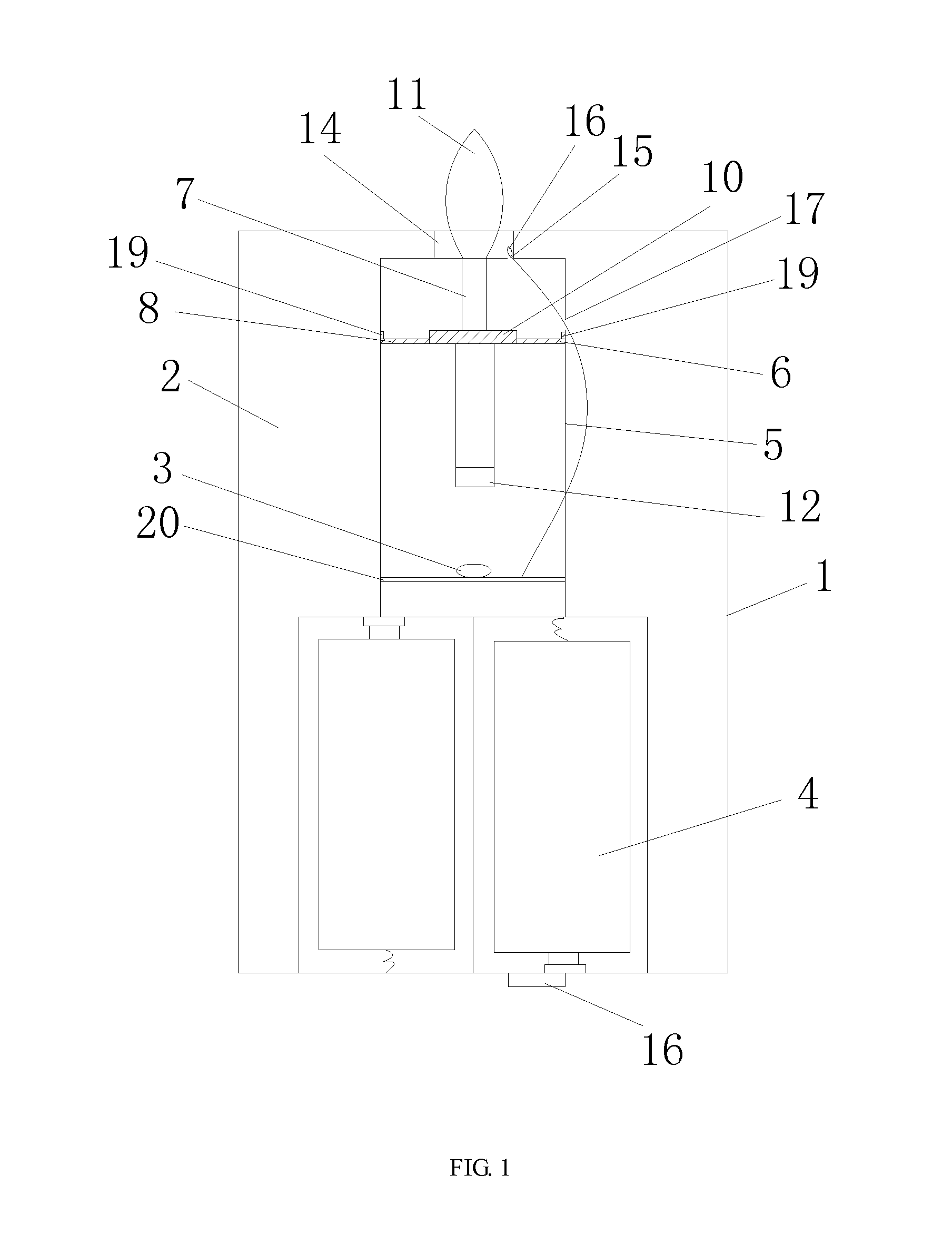
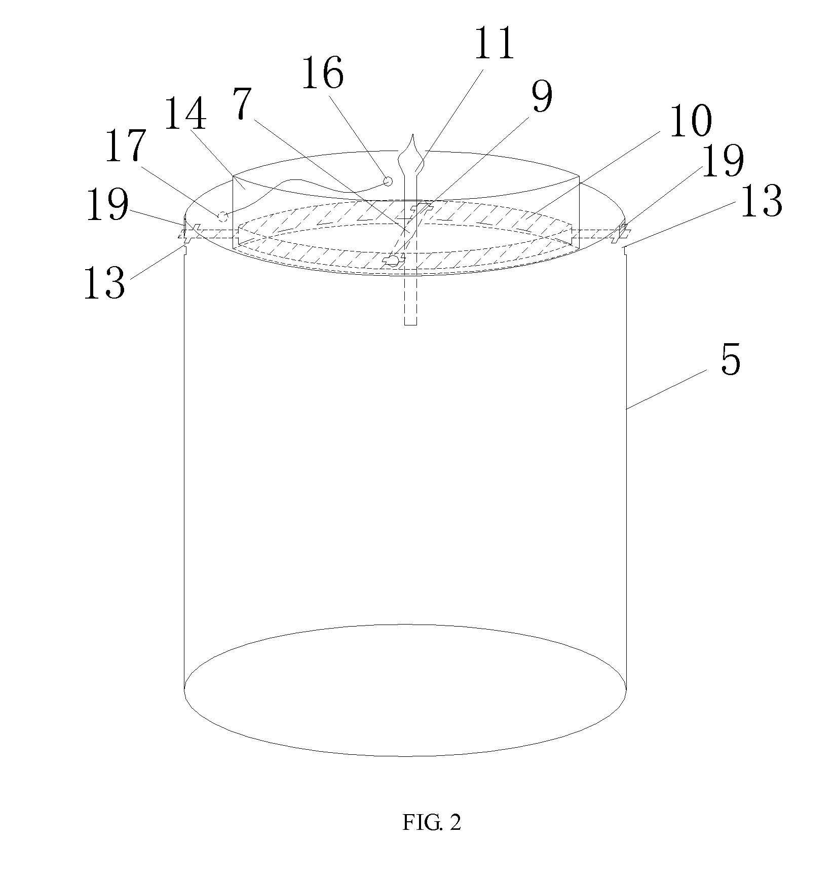
[0020]As shown in FIGS. 1, 2, 3 and 4, a swingable electronic candle comprises a candle body 1, whose inside is a cavity 2. Inside the cavity 2 is disposed with a candlewick. The candlewick includes a candle end and an electromagnetic coil 3 underneath the candle end. The electromagnetic coil 3 is mounted on a chip 20 and the chip 20 is connected with a drive circuit.

[0021]The electromagnetic coil 3 is driven by the drive circuit, which is connected with a power supply 4. The candle end includes a support 5 made of a hollow cylinder, a support frame 6 movably hung to the support 5 and a candlewick 7 supported by the support frame 6. The upper end of the hollow cylinder is disposed with a gap 13 to support a large support axis 8. The support frame 6 includes the large support axis 8 and a small support axis 9 that cross with each other with an angle of 90°. The large support axis 8 is disposed with a hollow frame 10 in the middle to support the small support axis 9. The sidewall of t...


PUM


Abstract

A swingable electronic candle includes a candle body having a cavity inside which is disposed a candlewick that includes a candle end and an electromagnetic coil underneath the candle end. The electromagnetic coil is driven by a drive circuit connected with a power supply. The candle end includes a support, a support frame and the candlewick. The support frame includes a large support axis and a small support axis that cross. The large support axis is disposed with a hollow frame to support the small support axis. Ends of the small support axis are movably supported in the hollow frame. Ends of the large support axis are movably hung to the support. The top of the candlewick is disposed with a flame head that is above the small support axis and the bottom of the candlewick is disposed with a magnet that is under the small support axis.

Description

FIELD OF THE INVENTION[0001]The present invention relates to an electronic candle, more particularly to a swingable electronic candle.BACKGROUND OF THE INVENTION[0002]Since electronic candles come into being, they become increasingly popular because they are safe, convenient, energy-saving and environmental friendly. Especially in European countries and American, they have the tendency to replace traditional candles.[0003]However, most of the existing electronic candles only have a light-emitting body. They are less dynamic and have low degree of simulation. Some swingable electronic candles are roughly made and the swingable heads are not flexible and likely to be clamped.SUMMARY OF THE INVENTION[0004]The objective of the present invention is to overcome the disadvantages of the prior art by providing a swingable electronic candle, which can swing freely and whose end can swing with 360°. The candle end is highly flexible and will not be clamped.[0005]The objective of the invention...

Claims


Application Information

Patent Timeline
IPC IPC(8): F21L4/00
CPCF21S6/001F21S10/046F21Y2101/00F21S9/02F21W2121/00F21Y2115/10
Inventor DING, YINGQI
Owner SHANGHAI Q MALL
Why Eureka
Try Eureka