Dry gas seal assembly

a technology of gas seals and gas bags, applied in the field of dry gas seals, can solve problems such as catastrophic failures, and achieve the effect of blocking the flow of gas

Active Publication Date: 2013-10-03
SOLAR TURBINES
View PDF3 Cites 18 Cited by
  • Summary
  • Abstract
  • Description
  • Claims
  • Application Information

AI Technical Summary

Problems solved by technology

Such materials may, however, fail and a failure can be catastrophic.

Method used


Image

  • Dry gas seal assembly
  • Dry gas seal assembly
  • Dry gas seal assembly

Examples


Embodiment Construction

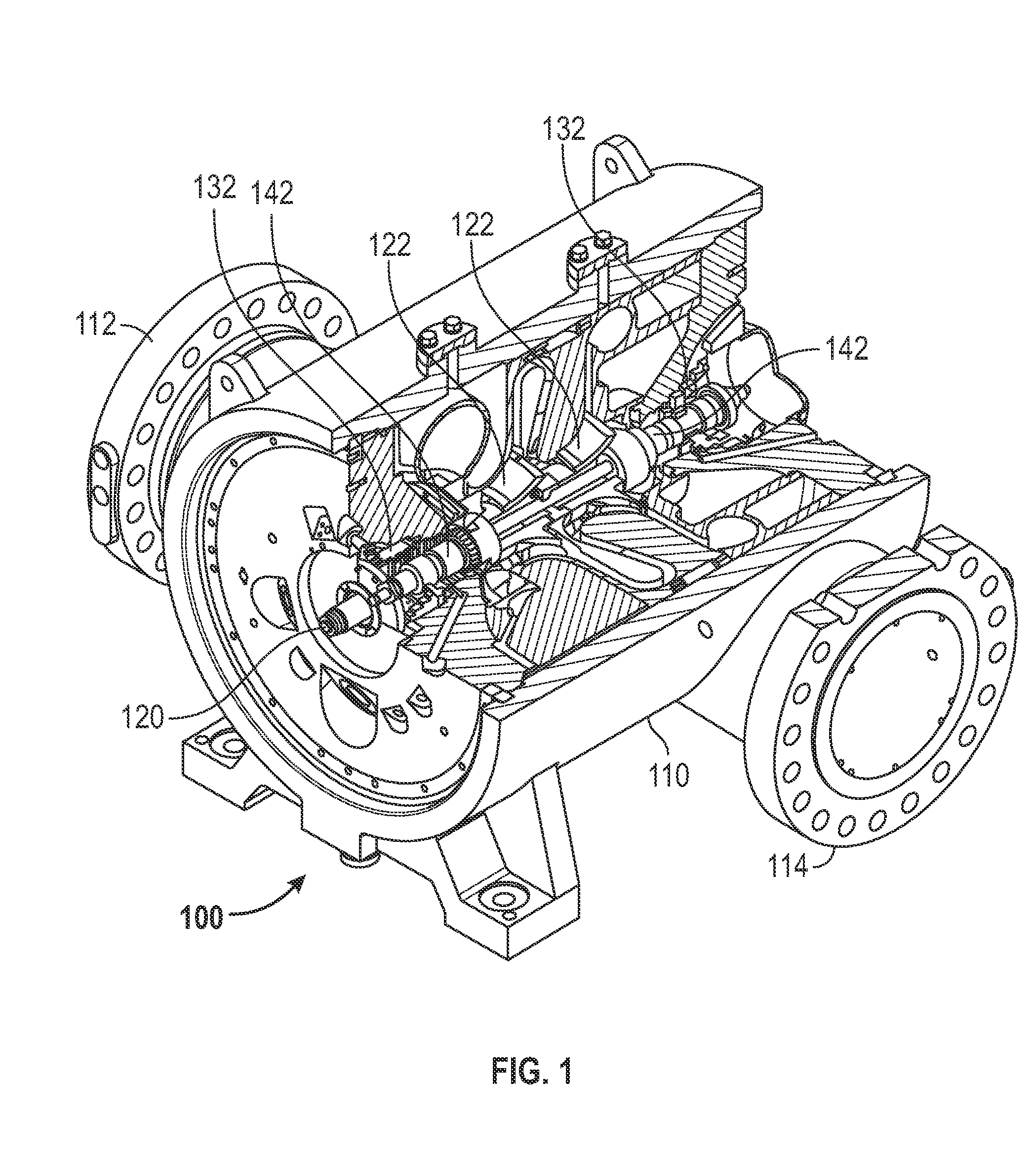
[0008]FIG. 1 is a cutaway illustration of an exemplary centrifugal compressor 100. Process gas enters the centrifugal compressor 100 at a suction port 112 formed on a housing 110. The process gas is compressed by one or more centrifugal impellers 122 mounted to a shaft 120. The compressed process gas exits the centrifugal compressor 100 at a discharge port 114 that is formed on the housing 110.

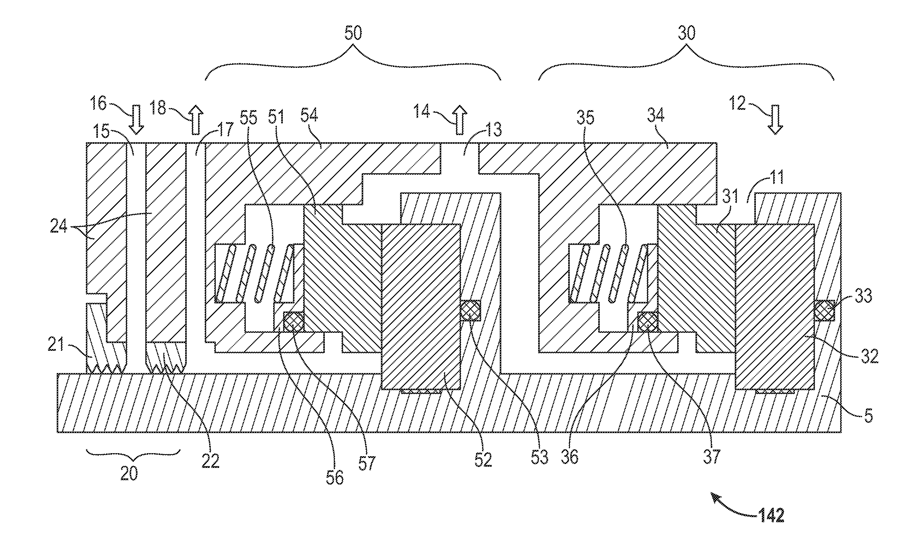
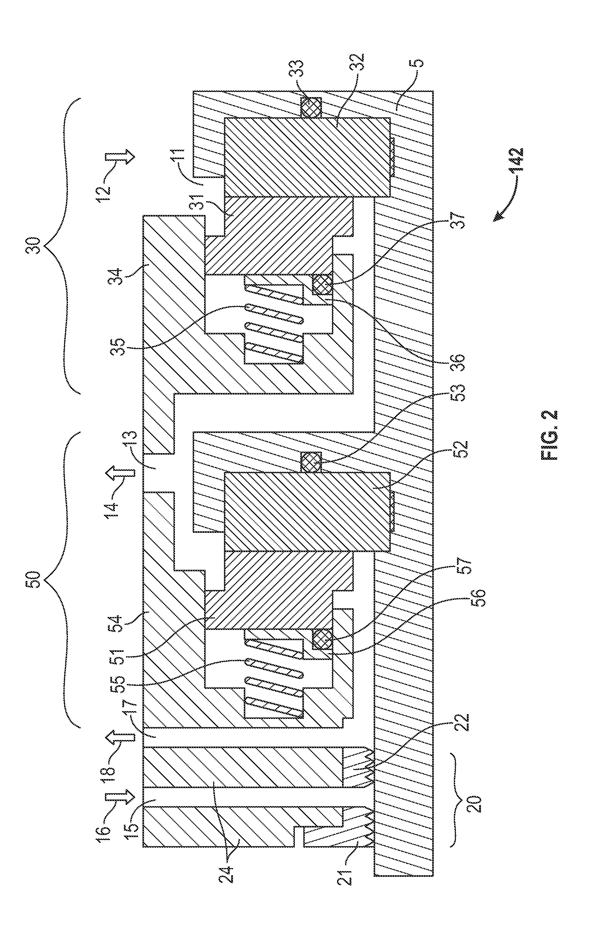
[0009]The shaft 120 and attached elements such as the centrifugal impellers 122 are supported by bearings 132 installed on axial ends of the shaft 120. Seal assemblies 142 are disposed about the shaft 120 inward of the bearings 132. The seal assemblies 142 seal high pressure inside the centrifugal compressor 100. Different designs may use more or fewer seal assemblies 142.

[0010]The seal assemblies 142 include primary and secondary seal stages. The primary seal stage normally operates to block the flow of the process gas out of the compressor. The secondary seal stage may be considered a backup...


PUM


Abstract

A seal assembly forms a barrier between a compressor's interior and exterior regions. The seals assembly includes a primary seal stage and a secondary seal stage. The primary seal stage is formed of materials chosen to effectively block flow of gas through the seal assembly. The secondary seal stage is formed of materials chosen to survive a failure of the primary seal stage.

Description

TECHNICAL FIELD [0001]The present disclosure generally pertains to a seal between relatively movable parts and more particularly to a tandem dry gas seal suitable for use with a centrifugal compressor.BACKGROUND [0002]Seal systems are used in a wide variety of rotary shaft devices, such as blowers, compressors, and pumps, which have critical sealing requirements. Dry gas seal systems provide a barrier between the gas in the working chamber, or process gas, and the external environment to minimize the loss of process gas to the environment. Seal systems may include two stages of seals arranged in tandem to improve reliability. Mosley and Haynes, in European Patent Application publication EP 0 701 074 A1, describe a dry gas seal with two face seal stages of the same construction.[0003]Dry gas seals operate with very small gaps or separations between opposed sealing surfaces. Brittle materials such silicon or tungsten carbide are used for some sealing surfaces to provide precise surfac...

Claims


Application Information

Patent Timeline
Patent Type & Authority Applications(United States)
IPC IPC(8): F04D29/10F16J15/34
CPCF16J15/008F04D29/122F16J15/3496F16J15/3484
Inventor BRAILEAN, GORDON E.
Owner SOLAR TURBINES
Why Eureka
Try Eureka