Double-chamber structure of dry gas seal testing cavity

A technology of dry gas sealing and test chamber, which is applied in the testing of machines/structural components, testing of mechanical components, measuring devices, etc. It can solve problems such as low detection efficiency, low work efficiency, and inability to remove products immediately

Inactive Publication Date: 2014-01-15
TIANJIN NIBOT SEALS TECH
View PDF0 Cites 9 Cited by
  • Summary
  • Abstract
  • Description
  • Claims
  • Application Information

AI Technical Summary

Problems solved by technology

[0003] The traditional cavity can only accommodate one set of dry gas seal, so the detection efficiency is low
In addition, due to the large amount of heat generated during the test, the product cannot be remo

Method used


Image

  • Double-chamber structure of dry gas seal testing cavity

Examples


Embodiment Construction

[0011] The present invention will be further described in detail below in conjunction with the accompanying drawings and through specific embodiments.

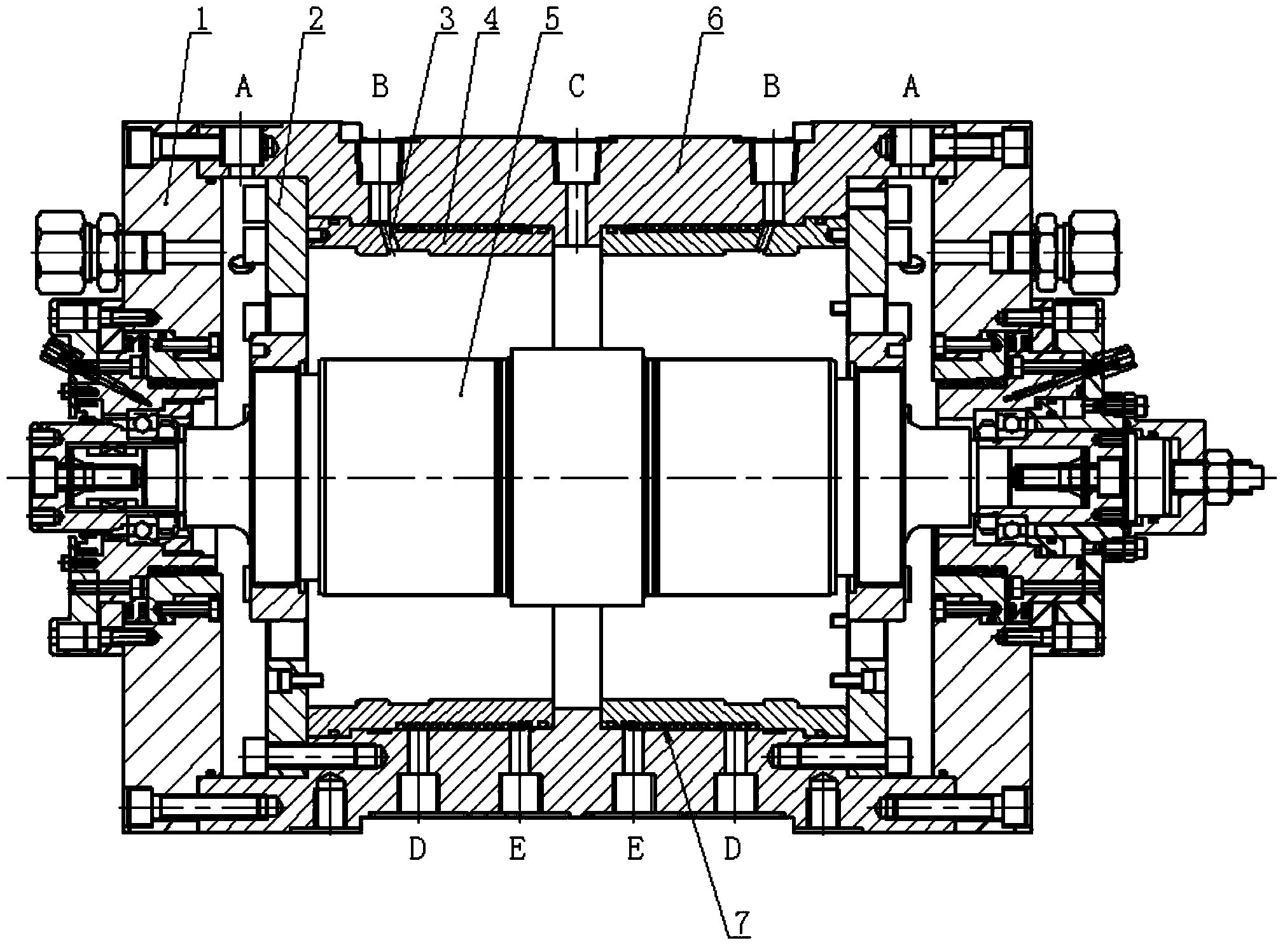
[0012] A double-chamber structure of a dry gas-tight test chamber, such as figure 1 As shown, it includes a chamber 6, a water jacket 4, and a main shaft 5. The chamber is a cylindrical barrel structure. Two water jackets are installed symmetrically on the same axis at both ends of the chamber. The two water jackets pass through the baffle respectively. 2. It is fixed together with the chamber, and a main shaft is coaxially installed in the two water jackets. The two ends of the main shaft are respectively installed together with the two ends of the chamber through the end cover 1. There is a dry gas seal assembly (not shown).

[0013] The outer edge of each water jacket is uniformly formed with a plurality of inclined holes 3 in the radial direction, and the outer edge of the cavity corresponding to each inclined hole is res...


PUM


Abstract

The invention relates to a double-chamber structure of a dry gas seal testing cavity. The double-chamber structure comprises chambers and a main shaft. Each chamber is of a cylindrical barrel structure, the two ends of each chamber are coaxially and symmetrically provided with two water sleeves, the two water sleeves and the chambers are fixedly arranged respectively, the main shaft is coaxially arranged in the two water sleeves, the two ends of the main shaft are movably arranged together with the chambers respectively through end covers, and dry gas seal components are arranged between the main shaft and the water sleeves respectively. The double-chamber structure can accommodate two dry gas seal components at the same time, so that work efficiency is effectively doubled, in addition, the dry gas seals in rotation can be quickly cooled through the water sleeves, a water inlet and a water return opening, the dry gas seals can be taken down right away after the testing is finished, and work efficiency is effectively improved.

Description

technical field [0001] The invention belongs to the technical field of dry gas sealing, in particular to a double chamber structure of a dry gas sealing test chamber. Background technique [0002] When performing dynamic and static tests, the dry gas seal is usually placed in a test chamber, and then the test chamber is placed on the test bench for testing. [0003] The traditional chamber can only accommodate one set of dry gas seal, so the detection efficiency is low. In addition, due to the large amount of heat generated during the test, the product cannot be removed immediately after the test is over, and the product to be tested must be replaced after the product and the test chamber have cooled to room temperature, resulting in low work efficiency. Contents of the invention [0004] The purpose of the present invention is to overcome the deficiencies of the prior art and provide a double-chamber structure of a dry gas-sealed test chamber with a simple structure and ...

Claims


Application Information

Patent Timeline
IPC IPC(8): G01M13/00
Inventor 李蕴哲段雪梅李勇沈向前吕秋斌
Owner TIANJIN NIBOT SEALS TECH
Why Eureka
Try Eureka