Landing gear vibration absorber and method of operating said landing gear vibration absorber

a technology of vibration absorber and landing gear, which is applied in the direction of shock absorber, manufacturing tools, transportation and packaging, etc., can solve the problem of reducing the response of the landing gear to the vibration of the helicopter

Inactive Publication Date: 2013-10-10
AIRBUS HELICOPTERS DEUT GMBH
View PDF10 Cites 14 Cited by
  • Summary
  • Abstract
  • Description
  • Claims
  • Application Information

AI Technical Summary

Benefits of technology

[0018]According to a preferred embodiment of the invention the at least one spring-mass system is located in the at least one cross tube, preferably the forward cross tube, at or near the skids of the landing gear. With the integrated at least one spring-mass system in the landing gear's cross tubes any impact on aerodynamics from the at least one spring-mass system is avoided. If the at least one spring-mass system has a mechanical failure, no parts will fall apart from the helicopter's landing gear.
[0019]According to a further preferred embodiment of the invention the at least one spring-mass system is symmetric relative to its centric mass.
[0020]According to a further preferred embodiment of the invention the at least one spring-mass system is a leaf spring mass system, particularly a sy

Problems solved by technology

Thus the at least one spring-mass system placed at or near antinodes of the landing gear significantl

Method used


Image

  • Landing gear vibration absorber and method of operating said landing gear vibration absorber
  • Landing gear vibration absorber and method of operating said landing gear vibration absorber
  • Landing gear vibration absorber and method of operating said landing gear vibration absorber

Examples


Embodiment Construction

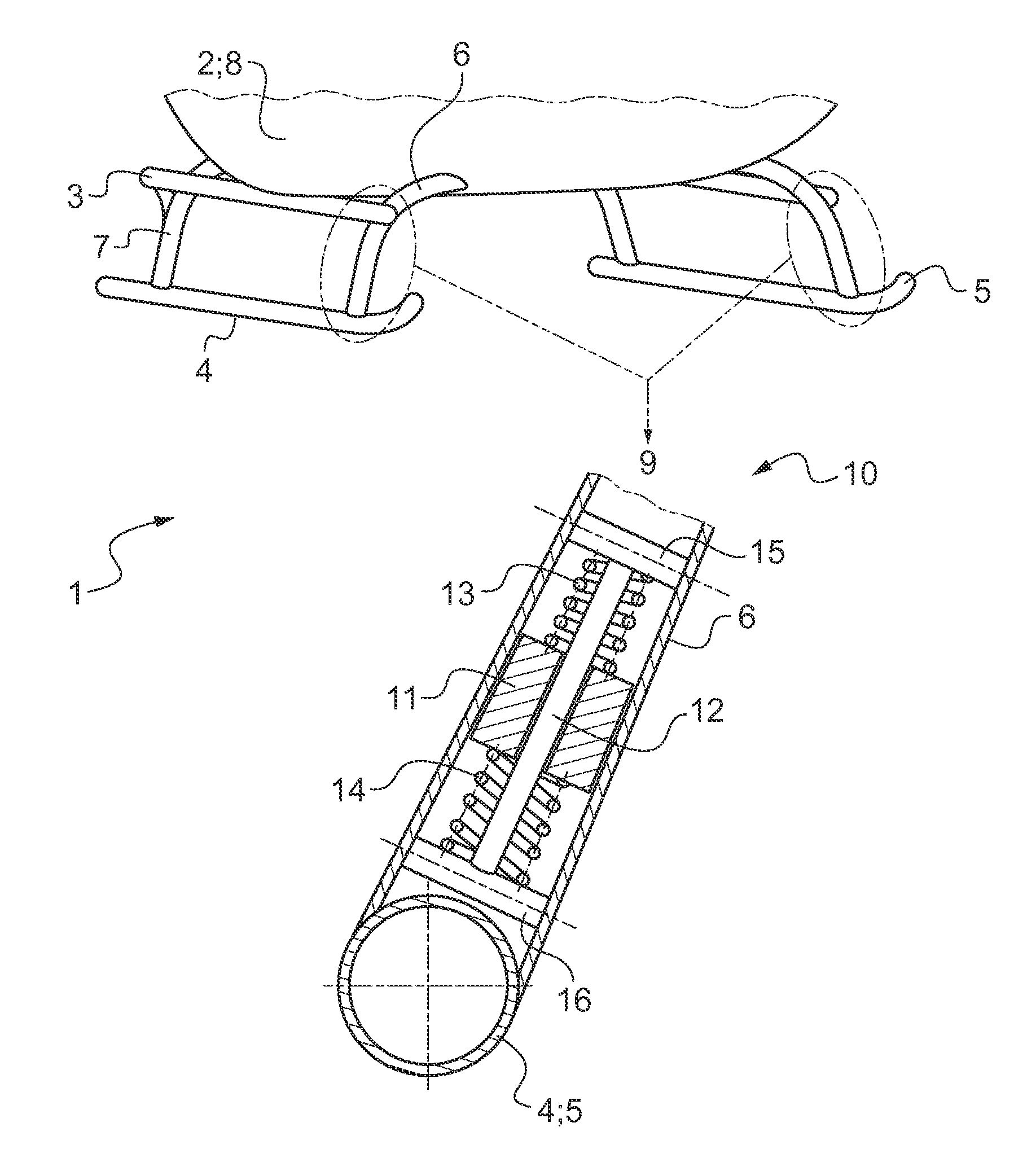
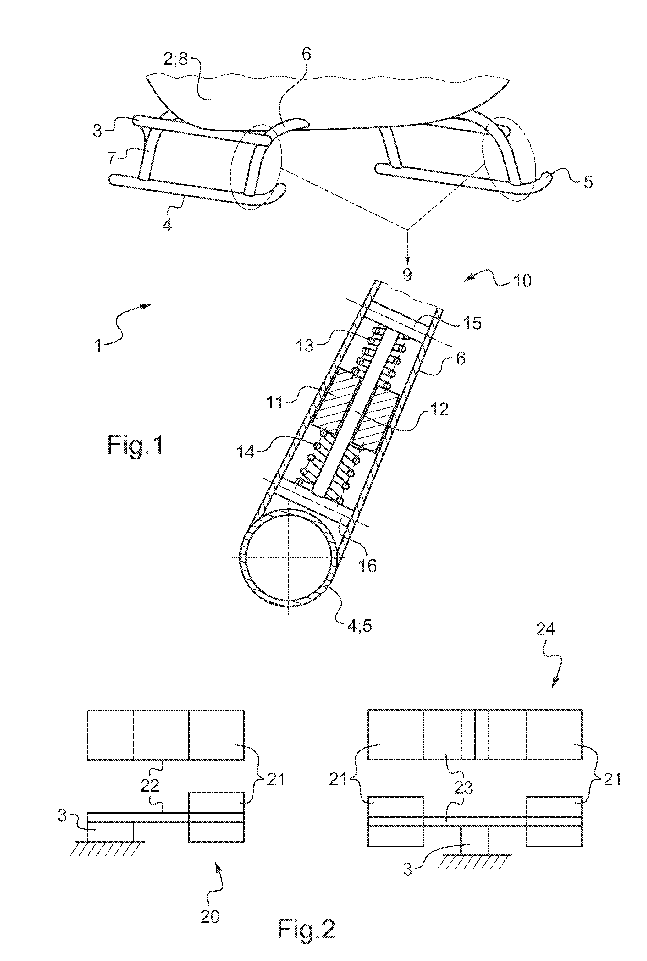
[0032]According to FIG. 1 a landing gear vibration absorber 1 of a helicopter 2 comprises a landing gear 3 with a pair of skids 4, 5, a forward cross tube 6 and a rearward cross tube 7 for mounting the skids 4, 5 to a fuselage 8 of the helicopter. The landing gear weight is in the range of 30 kg.

[0033]A linear spring-mass system 10 is mounted into the forward cross tubes 6 on either side of the landing gear 3 near to the connections between the skids 4, 5 and the forward cross tube 6. The linear spring-mass system 10 comprises a cylindrical mass 11 around a coaxial shaft 12. An upper spiral spring 13 and a lower spiral spring 14 are coaxially arranged around the shaft 12 on either side of the cylindrical mass 11. The upper spiral spring 13 abuts against an upper abutment 15 and the lower spiral spring 14 abuts against a lower abutment 16 next to the skid 4, 5 of the landing gear 3. The cylindrical mass 10 is supported by the upper spiral spring 13 and the lower spiral spring 14 at i...


PUM

PropertyMeasurementUnit
Massaaaaaaaaaa
Frequencyaaaaaaaaaa

Abstract

A landing gear vibration absorber (1) of a helicopter (2) with a landing gear (3) comprising a pair of skids (4, 5) and at least one cross tube (6, 7) for mounting the skids (4, 5) to a helicopter's fuselage (8). At least one spring-mass system (10, 20, 24) is mounted to the landing gear (3). Said at least one spring-mass system (10, 20, 24) is tuned to the helicopter's main excitation frequency and said at least one spring-mass system (10, 20, 24) being located at or near at least one antinode of the landing gear (3). The invention is related as well to a method of operating a landing gear vibration absorber (1) of a helicopter (2).

Description

CROSS REFERENCE TO RELATED APPLICATIONS[0001]This application claims priority to European patent application No. EP 400066.4 filed Dec. 21, 2011, the disclosure of which is incorporated in its entirety by reference herein.BACKGROUND OF THE INVENTION[0002](1) Field of the Invention[0003]The invention is related to a landing gear vibration absorber with the features of claim 1 and to a method of operating said landing gear vibration absorber with the features of claim 10.[0004](2) Description of Related Art[0005]It is known to attenuate or absorb the vibration of a rotorcraft by means of active or passive attenuator or absorber devices; passive devices are resonators tuned to a determined frequency, while active devices rely on an actuator that is controlled so as to deliver forces that oppose measured vibration.[0006]The document U.S. Pat. No. 7,461,729 A discloses a device for suspending a battery of an aircraft capable of providing a vibration attenuator system. The device includes...

Claims


Application Information

Patent Timeline
IPC IPC(8): B64C27/00
CPCB64C27/001B64C2025/325Y10T29/49764F16F7/116B64C2027/005B64C25/32B64C25/58F16F15/06
Inventor RAMMER, RAPHAELZNIKA, PETER
Owner AIRBUS HELICOPTERS DEUT GMBH
Why Eureka
Try Eureka