Flexible touch screen display

a touch screen display and flexible technology, applied in the field of flexible touch screen display, can solve the problems of reducing the optical clarity of the display, and the display is not flexible in a conventional same, and achieve the effect of reducing the thickness of the overall touch screen structure of the device configuration

Inactive Publication Date: 2013-10-10
FLEXENABLE LTD
View PDF13 Cites 11 Cited by
  • Summary
  • Abstract
  • Description
  • Claims
  • Application Information

AI Technical Summary

Benefits of technology

[0011]In embodiments of the invention, because the touch screen component is positioned below the device structure there is substantially no impairment of the optical clarity of the display. Moreover a user can operate the flexible resistive touch screen display device from the upper, viewing side, therefore making the device easier to use than one in which the rear surface of the display is employed as the touch pad, and enabling a wider range of applications for the device.
[0014]As previously mentioned, typically the display includes a backplane comprising an array of transistors, and in preferred embodiments the structure is configured so that the backplane is located on (within or substantially adjacent) a neutral axis or surface (plane) of the device—that is the neutral axis of the device is adjacent or within a layer comprising the array of thin film transistors (TFTs). This reduces the mechanical strain on the transistors during use of the touch sensitive display device. Alternatively the touch sensor may be on (within, or substantially adjacent) the neutral axis or surface.
[0026]Accordingly, one embodiment of the present invention provides a device configuration for a resistive touch screen structure which incorporates a flexible display medium in contact with a flexible backplane. The backplane comprises an active matrix array of transistors and is formed on a flexible substrate. The flexible display medium is brought in contact with the flexible backplane either through direct deposition of a display active layer, such as an organic light-emitting diode or liquid-crystal display cell, or through lamination with a display medium, such as, but not limited to, an electrophoretic, electrochromic or electronic paper display medium on flexible countersubstrate. The display comprising the flexible backplane and the flexible display medium is laminated on top of a resistive touch screen sensor, which is operable from the top by applying pressure to the display media. By locating the touch screen sensor behind the flexible display the optical quality of the display is not impaired by the finite optical absorption and reflection of the metallic and dielectric layers of the touch screen sensor. In embodiments no optical design compromise, or optical engineering of the display or the touch screen is necessary to integrate the touchscreen functionality with the display.
[0028]In a further embodiment the thickness of the overall touch screen structure of the device configuration may be reduced by eliminating the need for an upper polymer film. In this configuration the upper conductive layer of the touch screen is deposited directly onto the bottom surface of the flexible backplane.
[0029]In another embodiment, the backplane is processed directly onto the upper conductive layer of the resistive touch screen component. This device design eliminates the need for a separate substrate to be used for the backplane but instead the transistors are fabricated onto the upper conductive layer of the touch screen component.

Problems solved by technology

A significant disadvantage with this configuration is a reduction in clarity caused by locating the touch screen component over the display media—the display must be viewed through the touch screen component thus significantly reducing the optical clarity of the display.
However this arrangement has the significant drawback that the display taint be mounted so that access to the rear of the display, on which is mounted the touch screen component, is provided.
However in these document the displays are not flexible in a conventional same; they are merely sufficiently thin to allow the slight deformation needed for the overall touch sensor functionality.

Method used


Image

  • Flexible touch screen display
  • Flexible touch screen display
  • Flexible touch screen display

Examples


Embodiment Construction

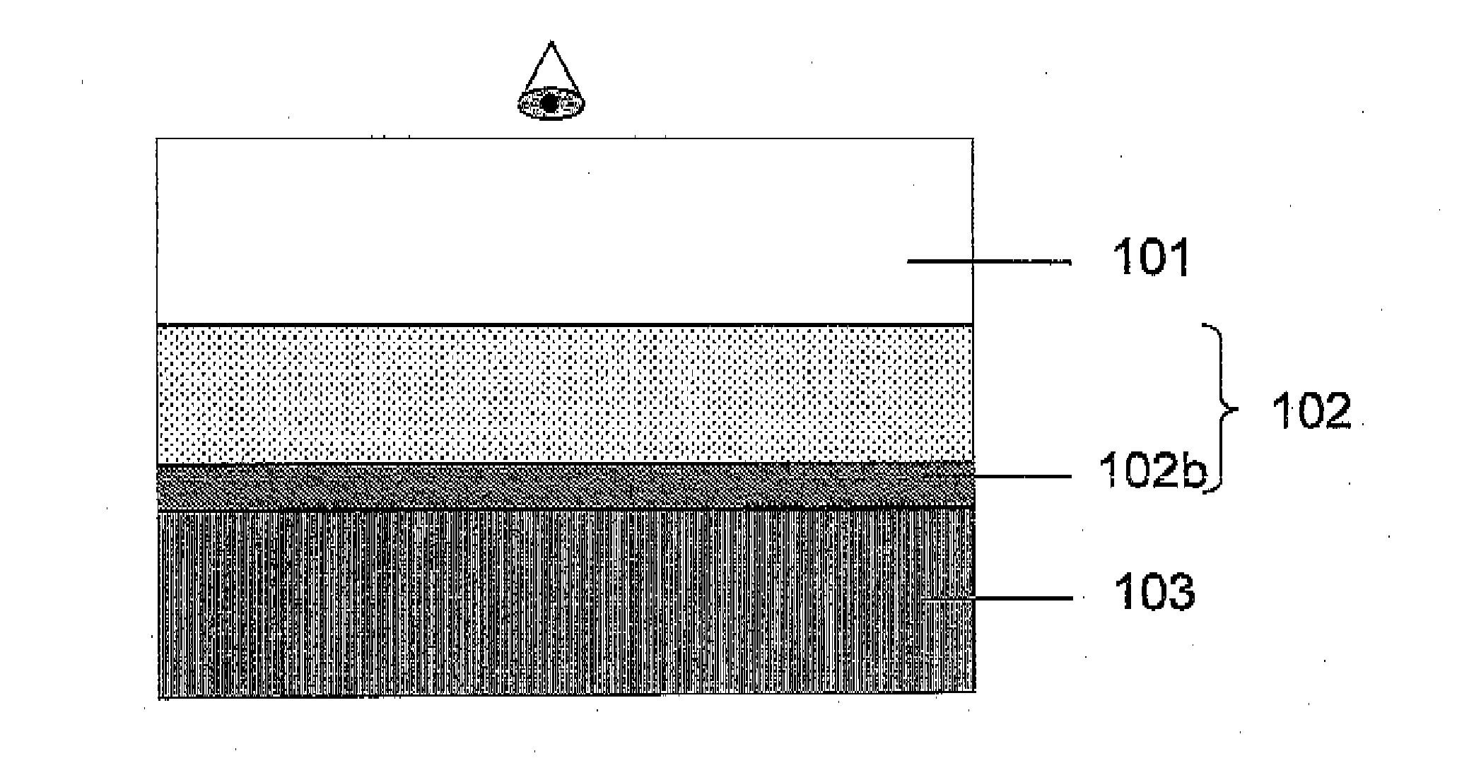
[0038]Broadly speaking we will describe a flexible display device with an integrated touch sensor, wherein a resistive touch screen component is placed underneath a flexible display without impairing the optical clarity of the display, hence yielding 100% optical clarity. The flexible display incorporates a flexible display medium in contact with a flexible backplane on a flexible substrate that allows for the device to be operable from the top by applying pressure to the display media. The flexible display medium and the display backplane are laminated over the resistive touch screen component.

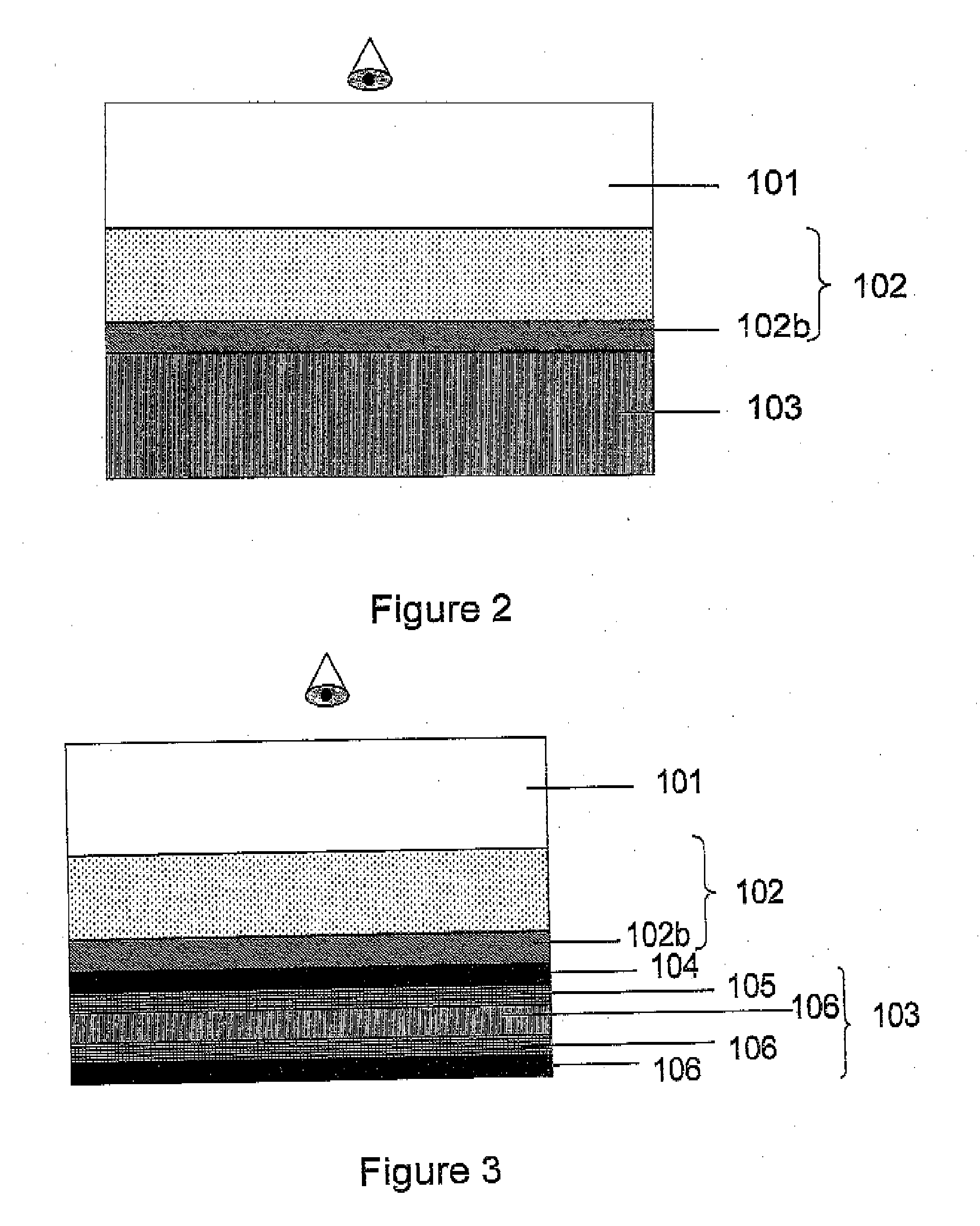
[0039]Referring to the drawings, FIG. 2 illustrates a device configuration for a resistive touch screen structure which incorporates a display media 101, laminated over a flexible backplane 102. The display media preferably has ultra thin dimensions as described further later. Preferably, an electrophoretic display media is incorporated within the device structure and is located over the back...


PUM


Abstract

A touch sensitive active matrix display device is provided. The device includes a display fabricated on a first flexible substrate, said display having a viewing surface. The device further includes a touch sensitive sensor including a second flexible substrate, under said display. The touch sensor is operated by touching said viewing surface of said display, and said combined display and touch sensitive sensor is flexible.

Description

CROSS-REFERENCE TO RELATED APPLICATIONS[0001]This application is a continuation of U.S. patent application Ser. No. 11 / 996,492, filed Aug. 16, 2010, entitled FLEXIBLE TOUCH SCREEN DISPLAY, which is the U.S. National Phase under 35 U.S.C. §371 of International Application No. PCT / GB2006 / 050220, filed Jul. 24, 2006, designating the United States and published in English on Feb. 1, 2007 as WO 2007 / 012899, which claims priority to United Kingdom Application No. 0515175.8, filed Jul. 25, 2005, and United Kingdom Application No. 0523125.3, filed Nov. 14, 2005.FIELD OF THE INVENTION[0002]This invention generally relates to integration of a flexible touch screen component, for example, using a resistive touch screen technology, with a flexible display to make a flexible combination device.DESCRIPTION OF RELATED ART[0003]There are several technologies known in the prior art for providing a sensor for a touch pad or touch screen. Such known technologies include capacitive technology, surface ...

Claims


Application Information

Patent Timeline
Patent Type & Authority Applications(United States)
IPC IPC(8): G06F3/041G06F3/044
CPCG06F3/0412G06F3/044G06F3/045
Inventor BURNS, SEAMUSSIDDIQUE, SHARJILJONES, SIMON
Owner FLEXENABLE LTD
Why Eureka
Try Eureka