Inkjet recording device

Active Publication Date: 2013-10-10
KONICA MINOLTA INC
View PDF1 Cites 24 Cited by
  • Summary
  • Abstract
  • Description
  • Claims
  • Application Information

AI Technical Summary

Benefits of technology

[0028]The present invention maintains the temperature of an image forming drum at a predetermined range of image-forming-drum set temperature. Therefore, how the dots spread on a recording medium can be controlled, and a recorded image having a constant smoothness and gloss can be obtained. Further, a recording head performs image formation on a recording medium on the image forming drum, instead of transferring the image formed on a drum to a recording medium as in a conventional case. This avoids image deterioration owing to the transfer, and can maintain high image quality. Further, this eliminates the need for a cleaning section which is required at the time of transferring of an image.
[0029]Further, since the device includes a first heating unit which heats a recording medium and a second heating unit which heats the image forming drum, the temperature of a recording medium can be raised to an intended temperature in a short period of time.
[0030]When the first heating unit includes a plurality of heating bodies and heats a recording medium while the temperature of each heating body is maintained within a predetermined range of heating-unit set temperature in the present invention, the temperature of a recording medium can be raised to an intended temperature in a short period of time f

Problems solved by technology

Such an inkjet recording system, however, has difficulty ejecting ink whose viscosity is not low.
As a result, when image

Method used


Image

  • Inkjet recording device
  • Inkjet recording device
  • Inkjet recording device

Examples


first embodiment

[0099]The best modes to carry out the present invention are described below with reference to the drawings. Although various limitations which are technically preferable to carry out the present invention are added in the embodiments below, the scope of the invention is not limited to the embodiments below and the examples shown in the drawings.

[Entire Configuration]

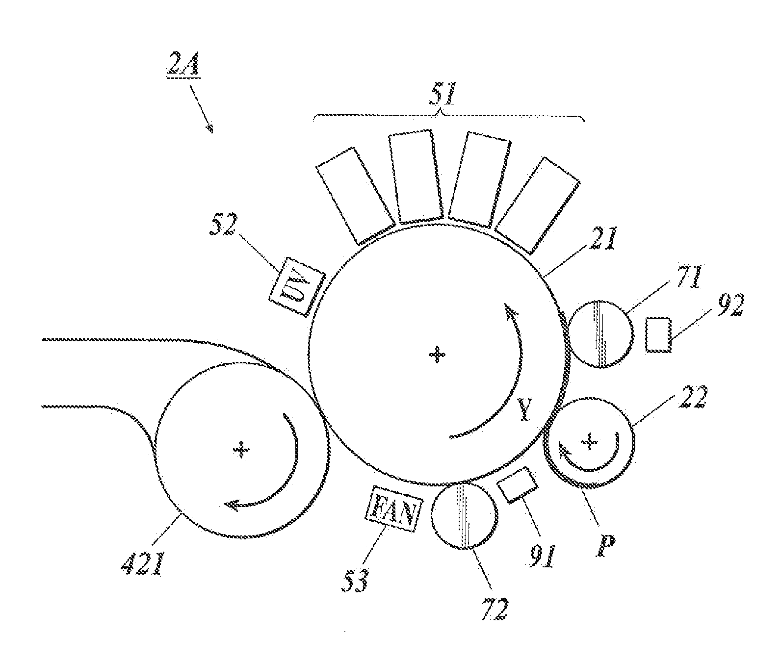
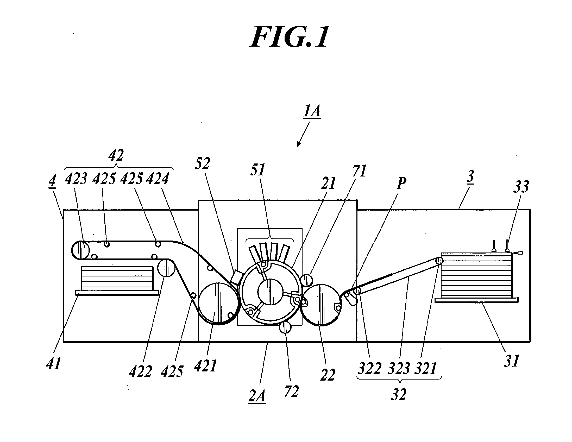
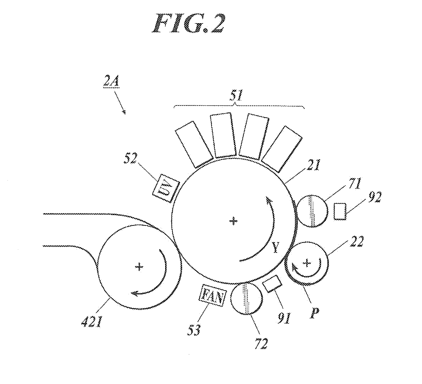
[0100]FIG. 1 is a typical view of the internal configuration of an inkjet recording device as an image forming device of the first embodiment of the present invention. As shown in FIG. 1, an inkjet recording device 1A of the present embodiment includes an image forming unit 2A, a paper feed unit 3 which feeds paper to the image forming unit 2A, and an accumulation unit 4 which accumulates a recording medium P on which image formation has been performed at the image forming unit 2A.

[Paper Feed Unit]

[0101]The paper feed unit 3 includes a paper feed tray 31 for storing recording media P, a conveying unit 32 for paper feedin...

second embodiment

[0259]An inkjet recording device 1B, which is the second embodiment of the present invention, is described with reference to the drawings. FIG. 11 is a typical view showing the internal configuration of an image forming unit 2B of an inkjet recording device 1B, and FIG. 12 is a block diagram showing the main control configuration of the inkjet recording device 1B. In the following explanations, only the points where the inkjet recording device 1B is different from the inkjet recording device 1A are described. The same components are indicated by the same reference number / letter, and repetitive explanations are omitted.

[0260]In the inkjet recording device 1B, a first recording medium temperature sensor 93 as a first recording medium temperature detector which detects the temperature of a recording medium P is disposed downstream of a heating roller 71 of a first heating unit and upstream of recording heads 51 around an image forming drum 21.

[0261]A second recording medium temperature...

third embodiment

[0301]An inkjet recording device 1C, which is the third embodiment of the present invention, is described with reference to the drawings. FIG. 17 is a typical view showing the internal configuration of an image forming unit 2C of an inkjet recording device 1C, and FIG. 18 is a block diagram showing the main control configuration of the inkjet recording device 1C. In the following explanations, only the points where the inkjet recording device 1C is different from the inkjet recording device 1A are described. The same components are indicated by the same reference number / letter, and repetitive explanations are omitted.

[0302]The inkjet recording device 1C is different from the inkjet recording device 1A in that the inkjet recording device 1C includes a dot diameter measuring section 69 disposed immediately downstream of a UV lamp 52 around an image forming drum 21. The dot diameter measuring section 69 is an image sensing device such as a CCD which images the dots on a recording mediu...


PUM


Abstract

An inkjet recording device includes an image forming drum, a recording medium supplying section, a recording head which ejects ink onto a recording medium, a first heating unit which heats the recording medium held on the drum before image recording, a second heating unit which heats the drum downstream of the position at which the recording medium is outputted after image recording and upstream of the supplying section, a heating-unit temperature detector, a drum temperature detector, and a heating control section. The heating control section performs heat control of the first heating unit such that the temperature detected by the heating-unit temperature detector falls within a predetermined set temperature range, and performs heat control of the second heating unit such that the temperature detected by the drum temperature detector falls within a predetermined set temperature range.

Description

TECHNICAL FIELD[0001]The present invention relates to an inkjet image recording device which ejects energy-ray curable ink onto a recording medium to record images.BACKGROUND ART[0002]In recent years, it has been possible to form high-definition images with an inkjet recording system having a relatively-simple structure. Such an inkjet recording system has become more and more versatile.[0003]Such an inkjet recording system, however, has difficulty ejecting ink whose viscosity is not low. As a result, when image formation is performed on a recording medium that does not absorb ink well, the phenomena called bleed and beading occur. The bleed is a phenomenon where inks are mixed between dots of different colors, and the beading is a phenomenon where the shades of the same color look like beads.[0004]In view of this, the problems have been solved with an image forming device including a head to eject ink whose viscosity is lowered at a high temperature, a transfer drum on which surfac...

Claims


Application Information

Patent Timeline
IPC IPC(8): B41J11/00
CPCB41J11/002B41J13/223B41J11/009B41J11/00214B41J11/00244
Inventor SUGAYA, TOYOAKIOBATA, MITSURUKIMOTO, HIROYAMURAMATSU, TAKASHIDATE, MASAKAZUMAEDA, AKIO
Owner KONICA MINOLTA INC
Why Eureka
Try Eureka