Quick installation multifunctional display
a multi-functional display and quick technology, applied in the direction of identification means, electrical apparatus casings/cabinets/drawers, instruments, etc., can solve the problems of high installation costs and heavy work of installing this large electronic display, and achieve the effect of reducing the work load and time for installing the quick installation multi-functional display and lowering the installation cos
- Summary
- Abstract
- Description
- Claims
- Application Information
AI Technical Summary
Benefits of technology
Problems solved by technology
Method used
Image
Examples
first embodiment
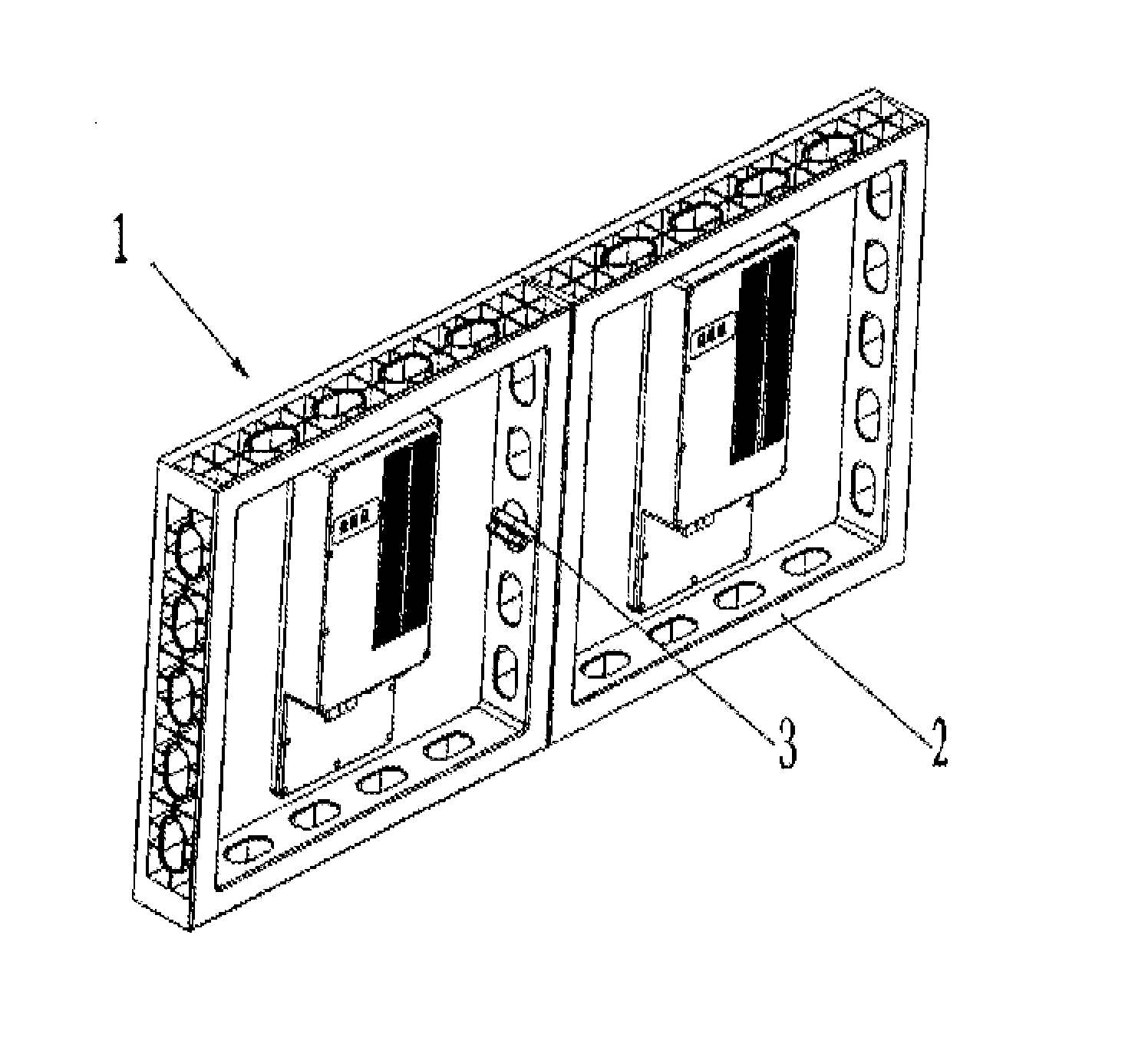
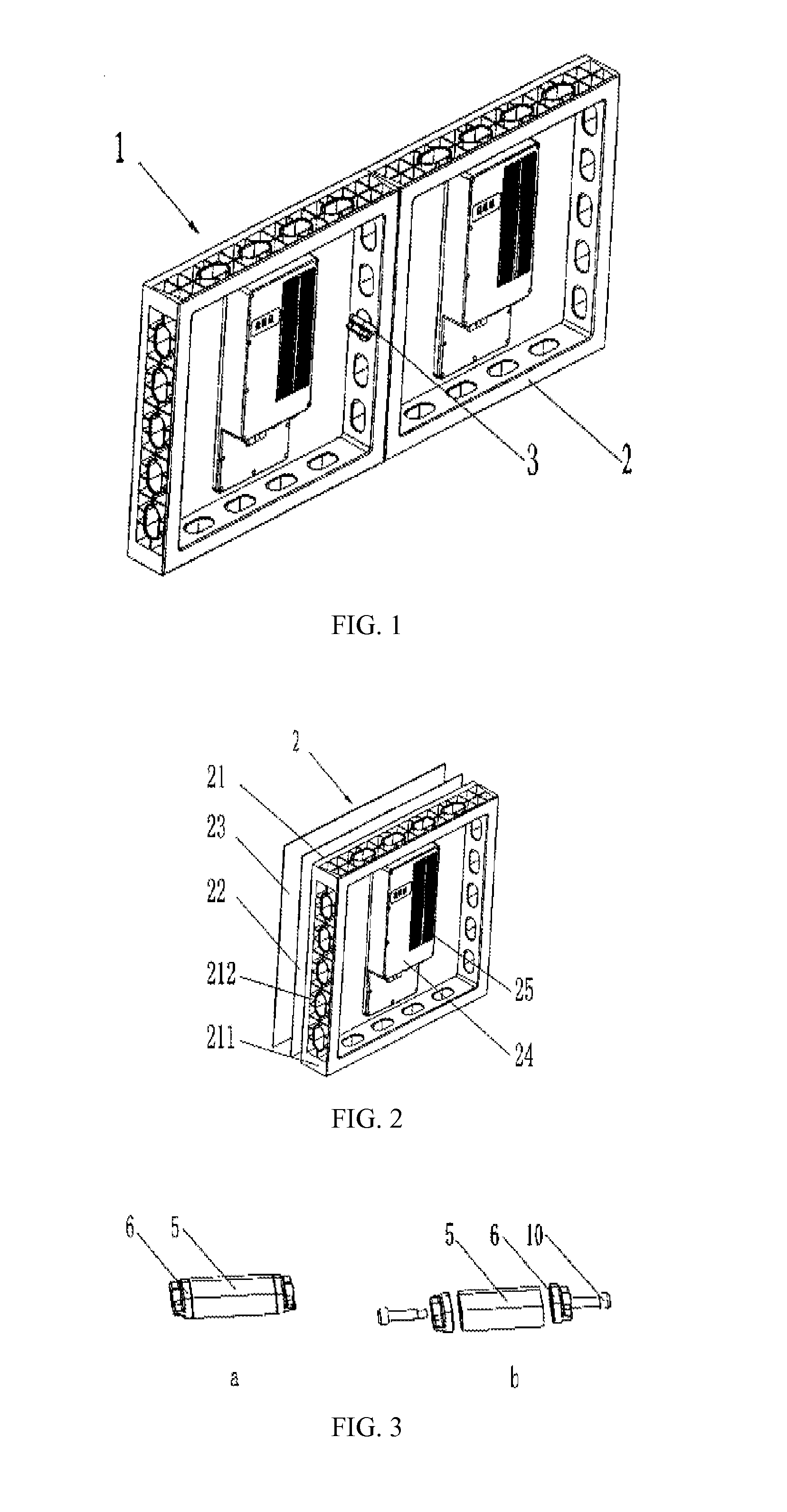
[0072]Furthermore, FIG. 1 and FIG. 3 illustrate the connecting piece in the present invention, the connecting piece 3 comprises a connecting seat 5, and twist locks 6 respectively connected to two ends of the connecting seat 5 through screws 10 and being rotatable relative to end surfaces of the connecting seat 5; the following operations could be carried out to lock the display units 2: sheathe said connecting seat 5 of the connecting piece 3 in the through-holes 212 of the side walls 211 of two adjacent frames 2, lean the twist locks 6 against the inside surfaces of the side walls of the two frames 2 and then rotate the twist locks 6 by a certain degree (90° is the best). Two steps of operating the connecting piece, that is, “one-sheathing and one-twisting”, could easily and quickly realize the installation or the disassembly of the display units.
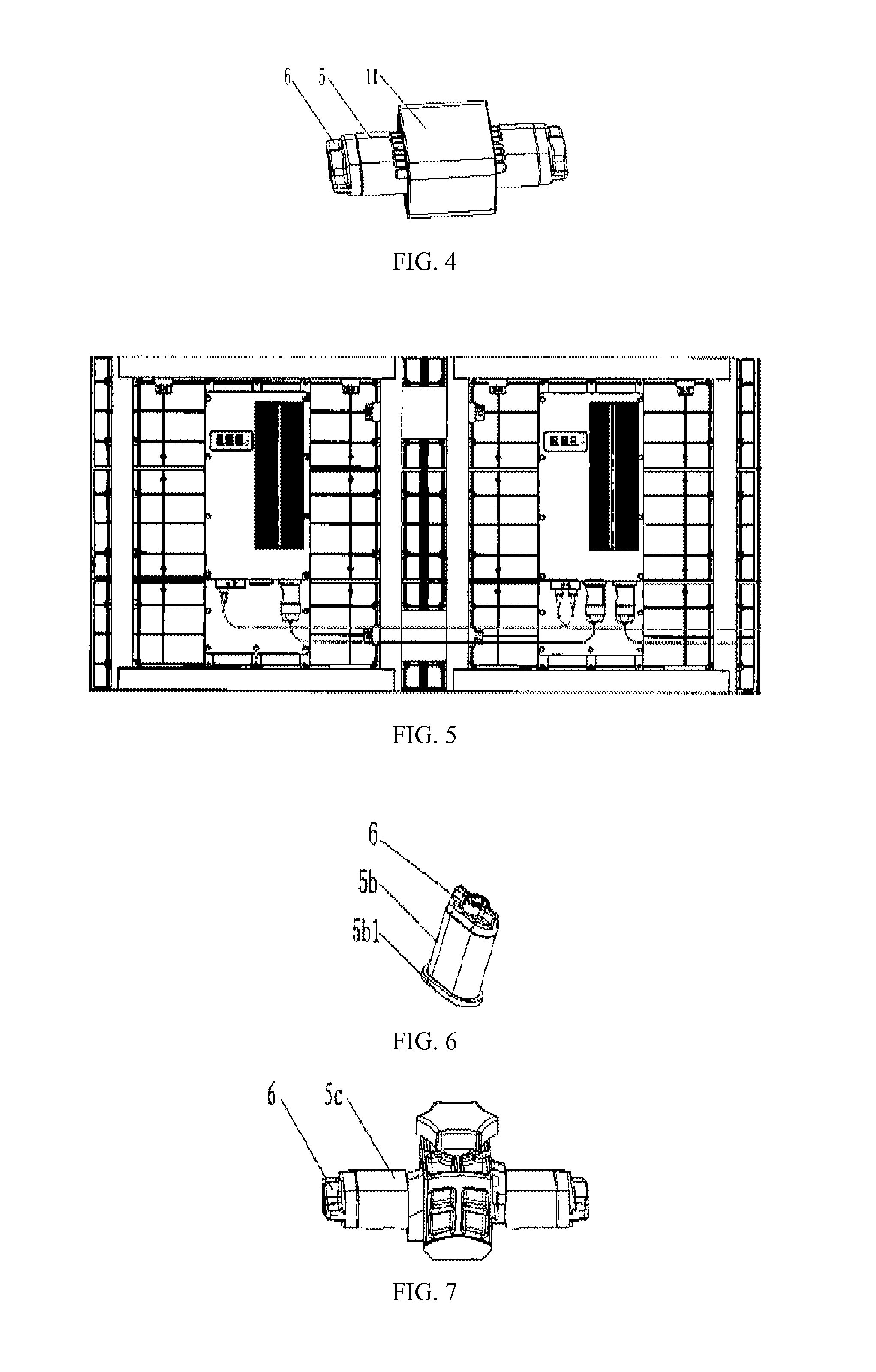
[0073]Referring to FIG. 4 and FIG. 5, generally, both the circuit board 22 and the cover 23 provided by the display unit 2 are protruded...
second embodiment
[0075]Furthermore, FIG. 6 illustrates the connecting piece in the present invention, the connecting piece 3 comprise a connecting seat 5b and a twist lock 6, the connecting seat 5b has a stop block 5b1 at one end thereof, while the other end, through a screw 10, is connected with the twist lock 6 (not shown in FIG. 6) which is rotatable to the connecting seat; the following operations could be carried out to lock up the display units 2: sheathe the connecting seat 5b in the though-holes 212 of the side walls 211 of two adjacent frames 2, lean the inside surface of the stop block 5b1 against the inside surface of the side wall of one of a frame 2 adjacent to the stop block, and lean the inside surface of the twist lock 6 against the inside surface of the side wall of another frame adjacent to the twist lock, then rotate the twist lock 6 by a certain degree (90° is the best) to lock the display units.
[0076]The connecting piece in the second embodiment of the present invention is usual...
third embodiment
[0077]Furthermore, FIG. 7 to FIG. 9 illustrate the connecting piece in the present invention, the connecting seat 5c comprises two connecting blocks 51a, 51b left-right opposite to each other, each of two connecting blocks providing with a turning block 52a, 52b on its end and the ends of the two connecting blocks being opposite to each other, a pressing block 53 sleeving outer sides of the turning blocks 52a, 52b, a locking block 54 arranged just below two turning blocks 52a, 52b, and a locking bolt 55, said pressing block 53 is in inverted-U shape, two turning blocks 52a, 52b are forward-backward symmetrically arranged and their two opposite sides are engaged with each other to be received in U-shaped notch of the pressing block 53; the top of said pressing block 53 has a hole in the centre thereof, the opposite sides of two turning blocks 52a, 52b are respectively provided with big-end-up half holes, and the locking block 54 has a screwed hole in the centre thereof, the locking b...
PUM
 Abstract
Description
Claims
Application Information
 - R&D
- Intellectual Property
- Life Sciences
- Materials
- Tech Scout
- Unparalleled Data Quality
- Higher Quality Content
- 60% Fewer Hallucinations
Browse by: Latest US Patents, China's latest patents, Technical Efficacy Thesaurus, Application Domain, Technology Topic, Popular Technical Reports.
© 2025 PatSnap. All rights reserved.Legal|Privacy policy|Modern Slavery Act Transparency Statement|Sitemap|About US| Contact US: help@patsnap.com


