
Trigger zones and dwell time analytics

a technology applied in the field of trigger zones and dwell time analytics, can solve the problem that the fencing application may not provide users with customized content, and achieve the effect of reducing interaction and increasing interaction

Inactive Publication Date: 2013-10-10
ENVIRONMENTAL SYST RES INST
View PDF5 Cites 385 Cited by
  • Summary
  • Abstract
  • Description
  • Claims
  • Application Information

AI Technical Summary

Benefits of technology

The invention relates to a method for receiving and processing trigger zone content on a computing device. The method involves determining the current geographic position of the device and sending the position data to a server. The server generates trigger zones based on the position data and sends the trigger zones to the device for processing. The device evaluates the trigger zones and sends a notification to the server when the requirements of a trigger zone are met. The method can also involve receiving position data from the device and determining if the device is within a threshold area of a trigger zone. The trigger zones can include requirements to be satisfied to trigger an event, such as digital content. The method can be performed using a computing device with a processor and computer-readable storage medium. The technical effect of the invention is to provide a way for triggering events based on the current geographic position of a device and the data associated with the location.

Problems solved by technology

Although there are many useful commercial applications for geo-fencing technologies, there are many problems associated with conventional geo-fence networks.
Some geo-fencing applications may not provide users with content customized to their particular needs.

Method used


Image

  • Trigger zones and dwell time analytics
  • Trigger zones and dwell time analytics
  • Trigger zones and dwell time analytics

Examples


Embodiment Construction

[0040]Embodiments of the invention are generally directed to systems, architectures of the systems, and methods for supporting geo-triggering, and dwell-time analytics.

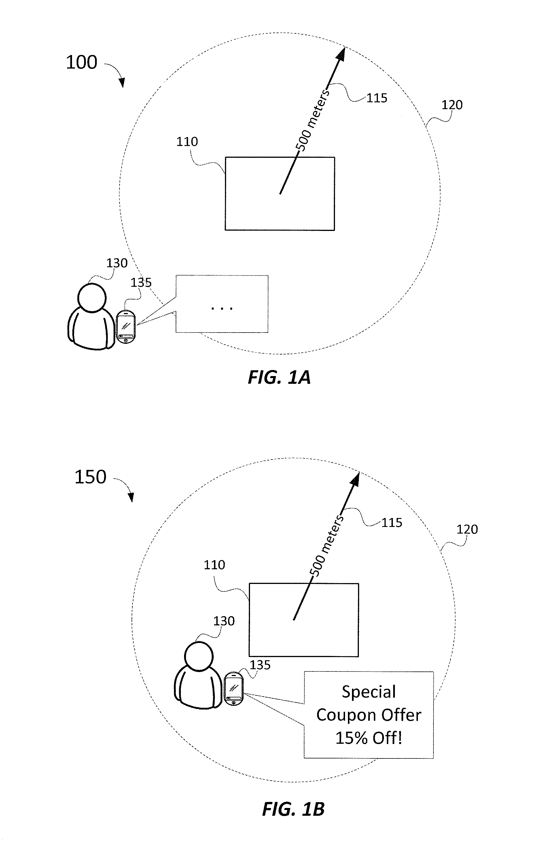
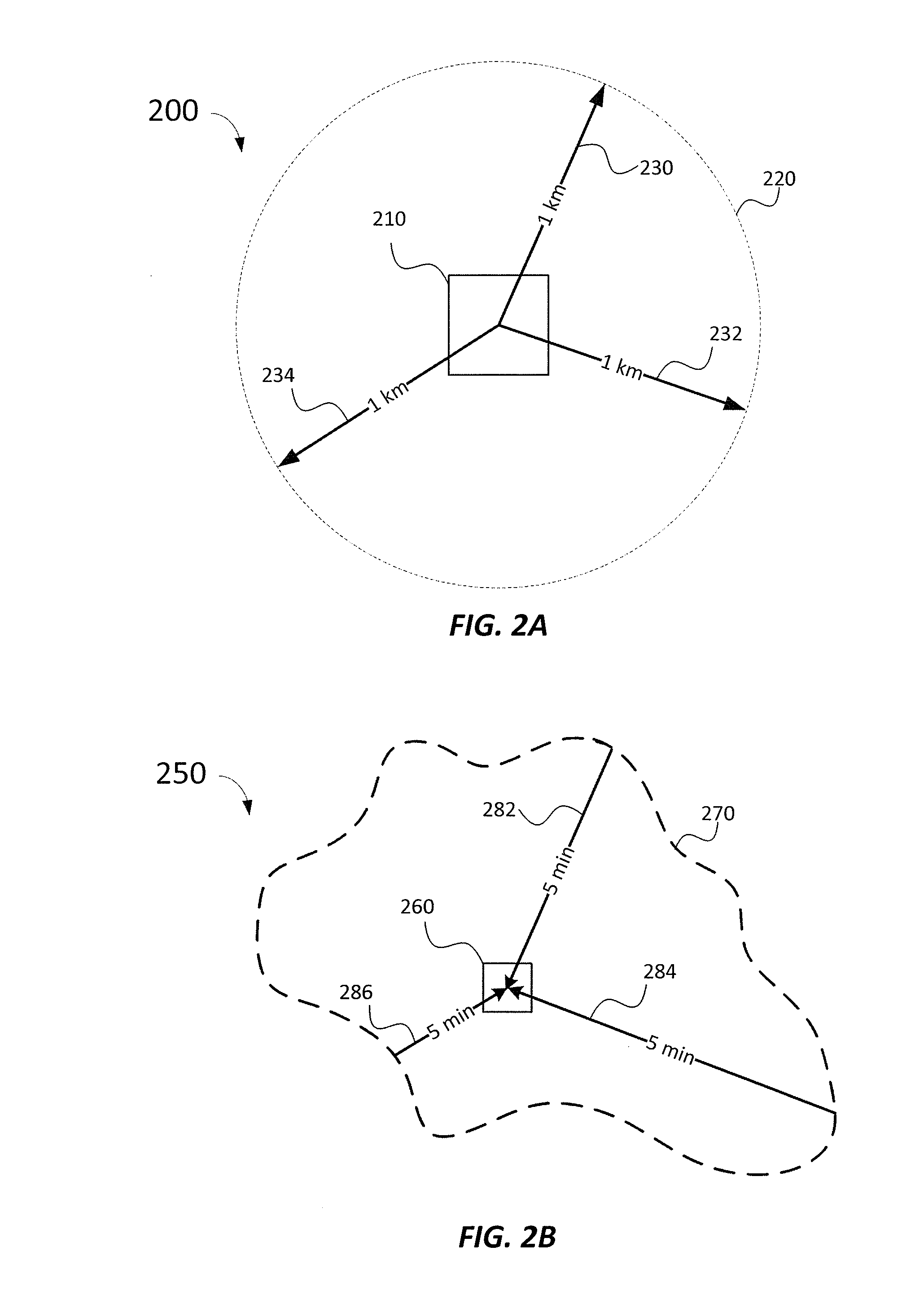
[0041]Certain embodiments of the invention related to a method of receiving and processing trigger zone and geo-trigger content on a computing device. Trigger zones can be relevant to a current geographic position of the computing device and can be characterized by a time-based boundary and one or more requirements to be satisfied to trigger an event. The computing device can evaluate trigger zones to determine if one the one or more requirements are satisfied, and trigger a trigger event if confirmed.

[0042]In some embodiments, a server computer can generate a dwell-time trigger zone based on an amount of time a computing device spends at a geographic location. The dwell time trigger zone can include trigger zone data corresponding to commercial aspects particular to the geographic location. The server computer can be...


PUM


Abstract

Certain embodiments of the invention related to a method of receiving and processing trigger zone and geo-trigger content on a computing device. Trigger zones can be relevant to a current geographic position of the computing device and can be characterized by a time-based boundary and one or more requirements to be satisfied to trigger an event. The computing device can evaluate trigger zones to determine if one the one or more requirements are satisfied and trigger an trigger event if confirmed. In some embodiments, a server computer can generate a dwell-time trigger zone based on an amount of time a computing device spends at a geographic location. The dwell time trigger zone can include trigger zone data corresponding to commercial aspects particular to the geographic location. The server computer can be configured to send the trigger zone and trigger zone data to the computing device for processing.

Description

CROSS-REFERENCES TO RELATED APPLICATIONS[0001]The present non-provisional U.S. patent application claims benefit under 35 U.S.C. §119 of U.S. Provisional Patent Application No. 61 / 585,776, filed on Jan. 12, 2012, and entitled “Trigger Zones and Dwell Time Analytics,” which is incorporated by reference in its entirety for all purposes.BACKGROUND[0002]The use of geo-fences in commercial applications has become more prevalent as the popularity and access to mobile electronics continues to increase. Geo-fencing can be configured to enable an action to be taken when a device enters or leaves a specific geographical area defined by the geo-fence. Some common uses of geo-fencing may include a to-do list application that can notify a user to buy bread when user nears a grocery store, a department store application configured to notify a user about a current sale on their favorite shirts when at or near a store branch, and more. In summary, user no longer have to launch their favorite depart...

Claims


Application Information

Patent Timeline
IPC IPC(8): H04W4/02H04W4/021
CPCH04W4/021
Inventor CASE, AMBER L.PARECKI, AARON D.
Owner ENVIRONMENTAL SYST RES INST
Learn More