
Touch panel and a manufacturing method thereof

a manufacturing method and touch panel technology, applied in the field of input interfaces, can solve problems such as loss and errors in data transmission, affecting the normal use of the touch panel, and achieve the effect of reducing the influence of signal crosstalk on the efficiency of the integral touch panel

Active Publication Date: 2013-10-17
TPK TOUCH SOLUTIONS (XIAMEN) INC
View PDF3 Cites 5 Cited by
  • Summary
  • Abstract
  • Description
  • Claims
  • Application Information

AI Technical Summary

Benefits of technology

This patent is about a touch panel that tries to improve the accuracy of touch signals by reducing interference between neighboring wires. The panel achieves this by setting up earhing lines between certain parts of the panel, which prevents signals from affecting each other and affecting the efficiency of the touch panel. This makes the touch panel more reliable and accurate.

Problems solved by technology

Moreover, since all the existing electronic products are designed with an Objective of being light thin, short and small is not enough space in a product for containing traditional input devices such as keyboard, mouse, etc., and especially, driven by the demand for humanized tablet PCs, touch panels have became a key component.
Signal crosstalk can cause loss and errors in data transmission, thereby affecting the normal use of the touch panel.

Method used


Image

  • Touch panel and a manufacturing method thereof
  • Touch panel and a manufacturing method thereof
  • Touch panel and a manufacturing method thereof

Examples


Embodiment Construction

[0023]For those skilled in the art to understand the present disclosure, numerous embodiments are described below, combined with drawings to minutely illustrate the matters of the disclosure and the purpose thereof.

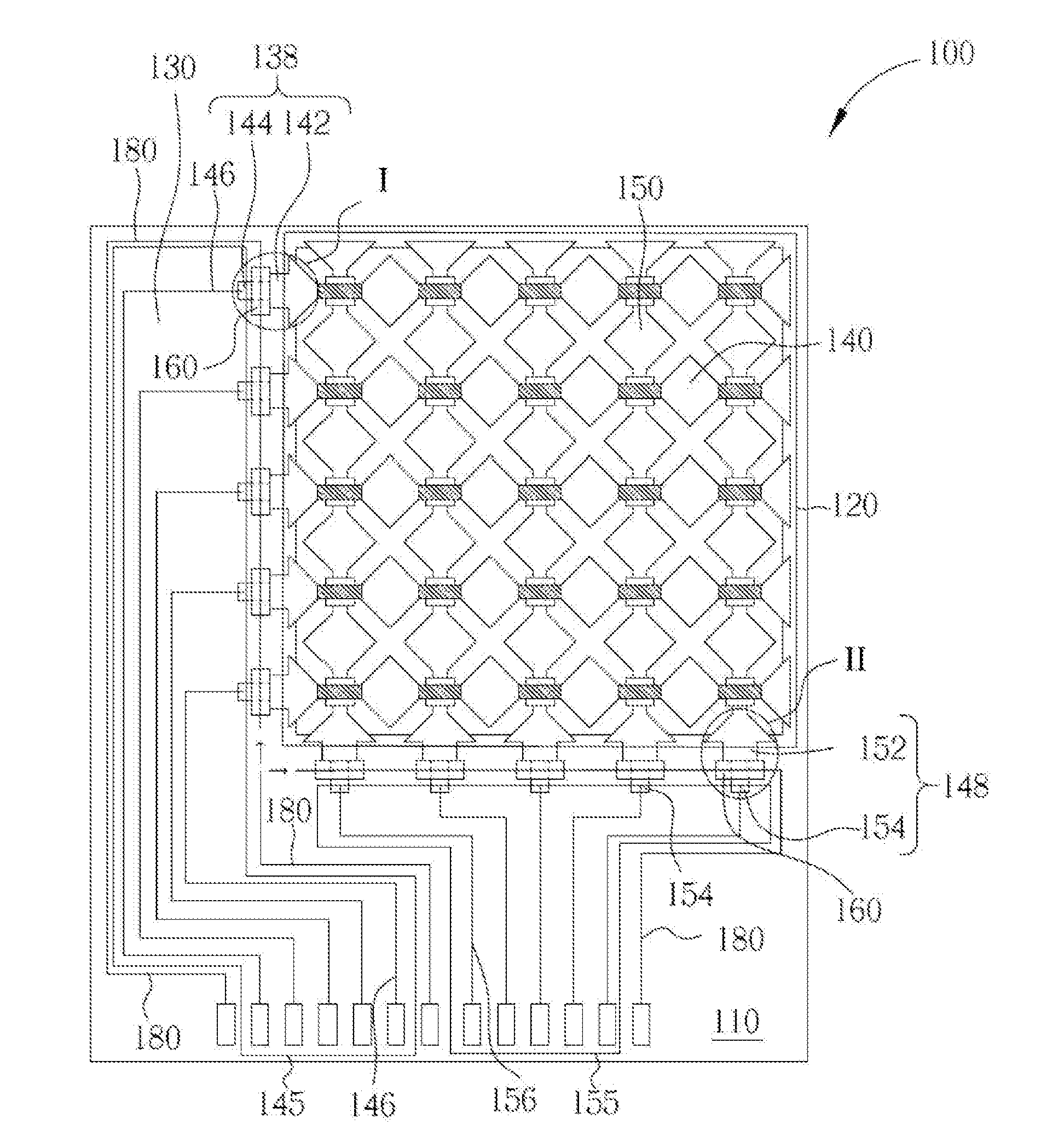
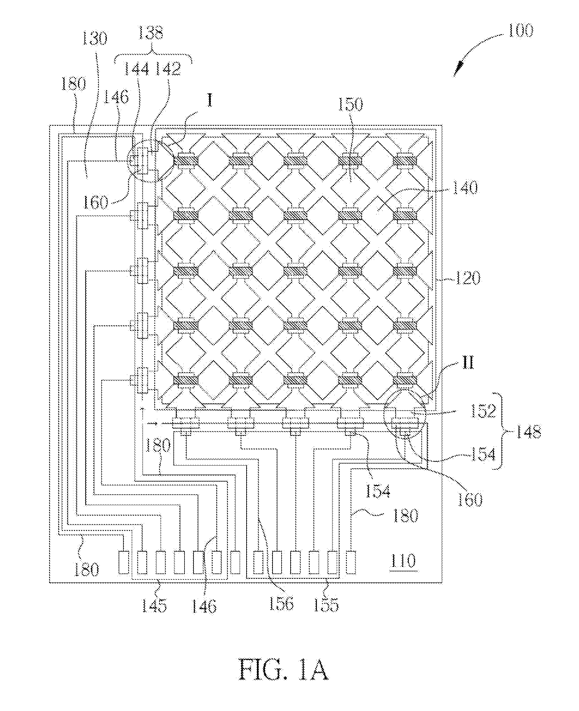
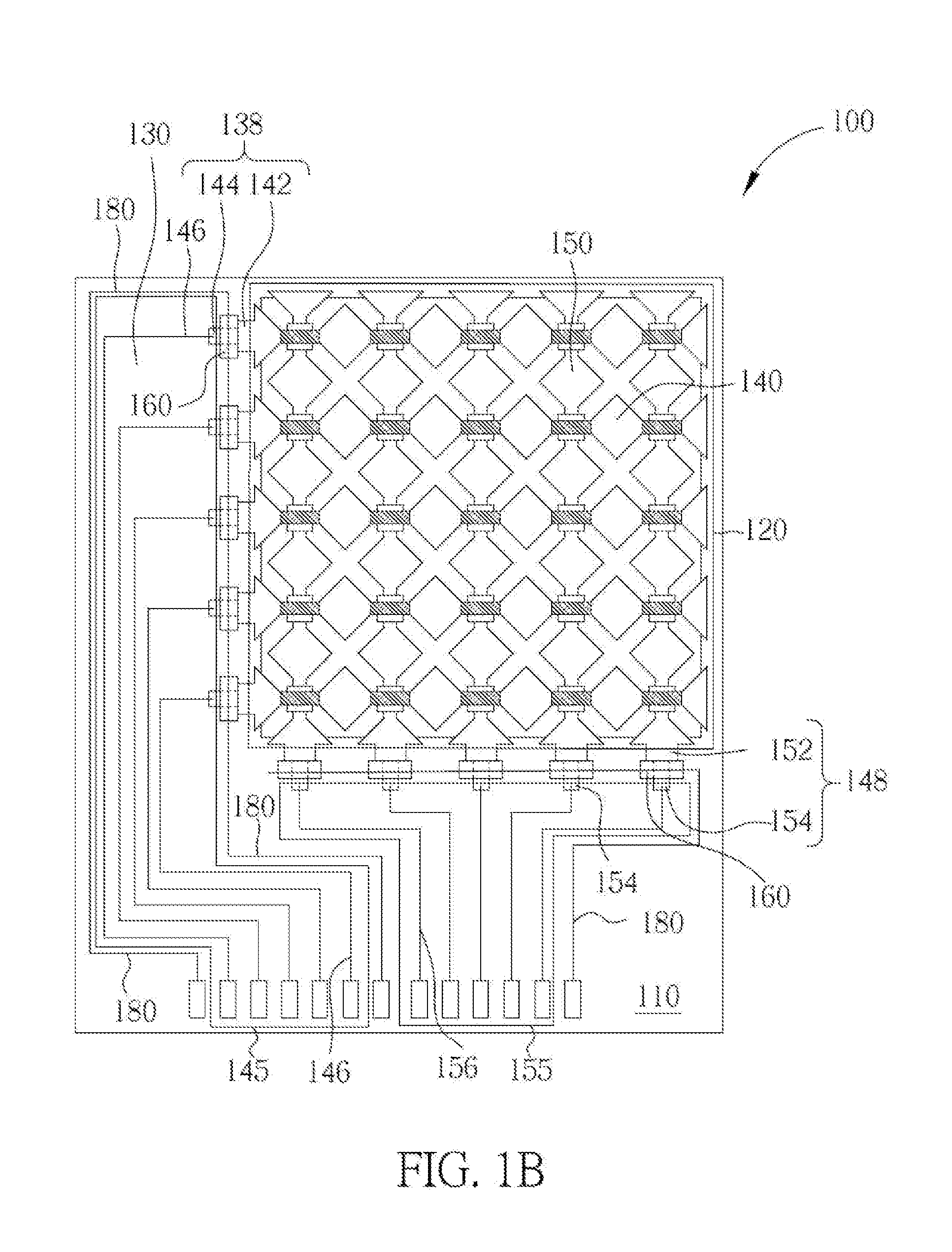
[0024]With reference to FIG. 1˜FIG. 3, FIG. 1A is a schematic top view of a first preferred embodiment of the present disclosure, a idle FIG. 1B and FIG. 1C are schematic top views of other Iwo modes of the first preferred embodiment of the present disclosure. FIG. 2A is a schematic enlarged view of part I of FIG. 1A and FIG. 2B is a schematic enlarged view of part II of FIG. 1A. FIG. 3A is a schematic sectional view of FIG. 2A along the line AA′, and FIG. 3B is a schematic sectional view of FIG. 2B along the line AA′. In order to make it convenient for illustration and fix easier understanding of the present disclosure, drawings of the present embodiment are only schematic drawings, and their detailed proportions can be adjusted according to design requirements.

[0025]As ...


PUM


Abstract

The present disclosure provides a touch panel which at least comprises a sensing area, a conductive wire area, and earthing lines. The conductive wire area surrounds the sensing area and is electrically connected to the sensing area, and the conductive wire area comprises a first conductive wire area and a second conductive wire area. The earthing lines are set between the first conductive wire area and the second conductive wire area. The touch panel can efficiently shield signal crosstalk between the first conductive wire area and the second conductive wire area by setting the earthing lines between the first conductive wire area and the second conductive wire area, thereby reducing the influence of signal crosstalk on efficiency of the touch panel.

Description

[0001]This application claims the benefit of Chinese application No 201210113781.6, filed on Apr. 17, 2012.BACKGROUND[0002]1. Technical Field[0003]The present disclosure relates to an input interface. More particularly, the present disclosure relates to a touch panel based input interface.[0004]2. Description of the Related Art[0005]In the present market of various consumer electronic products, touch panels are being widely used in portable electronic products such as PDAs, mobile phones, notebooks and tablet PCs to act as an interface for information communication. Moreover, since all the existing electronic products are designed with an Objective of being light thin, short and small is not enough space in a product for containing traditional input devices such as keyboard, mouse, etc., and especially, driven by the demand for humanized tablet PCs, touch panels have became a key component.[0006]A conventional touch panel usually comprises a substrate, on which a sensing area and a ...

Claims


Application Information

Patent Timeline
IPC IPC(8): H01H9/12
CPCH01H9/12G06F3/0446G06F3/041G06F2203/04103
Inventor XIE, YANJUNJIANG, YAU-CHENLAI, BINSHI, ENSHI
Owner TPK TOUCH SOLUTIONS (XIAMEN) INC
Learn More