Overhead light fixture and related method

Active Publication Date: 2013-10-17
IDEAL IND LIGHTING LLC
View PDF14 Cites 2 Cited by
  • Summary
  • Abstract
  • Description
  • Claims
  • Application Information

AI Technical Summary

Benefits of technology

[0007]This invention is an overhead LED light fixture which includes: a base member having a top and a bottom, having an outward frame, and defining a pass-through opening; a sleeve secured at the top of the base member for alignment with the pass-through opening; and a driver-tray assembly having a bottom member engage

Problems solved by technology

When such light fixtures are positioned primarily above the canopy

Method used


Image

  • Overhead light fixture and related method
  • Overhead light fixture and related method
  • Overhead light fixture and related method

Examples


Example

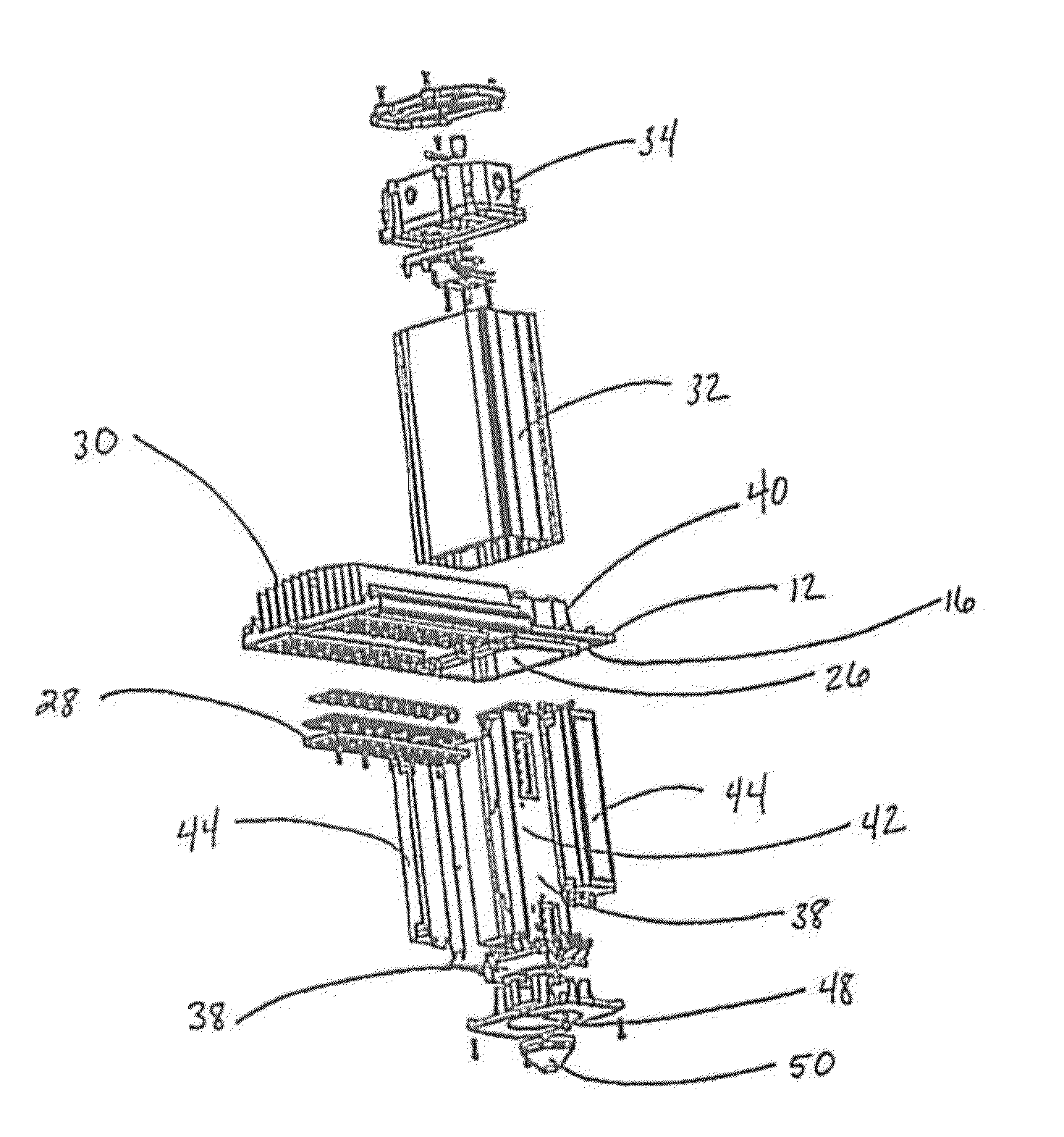
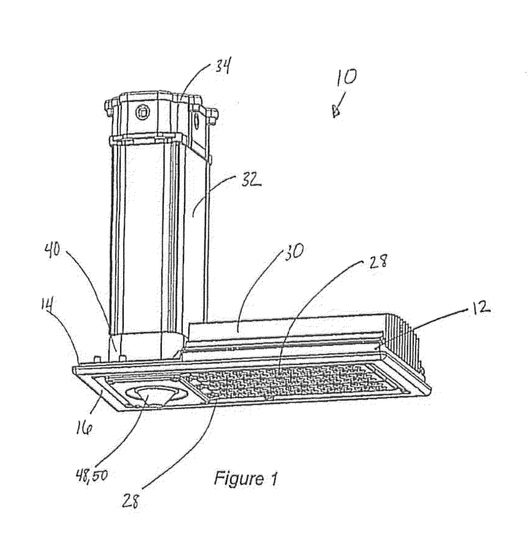
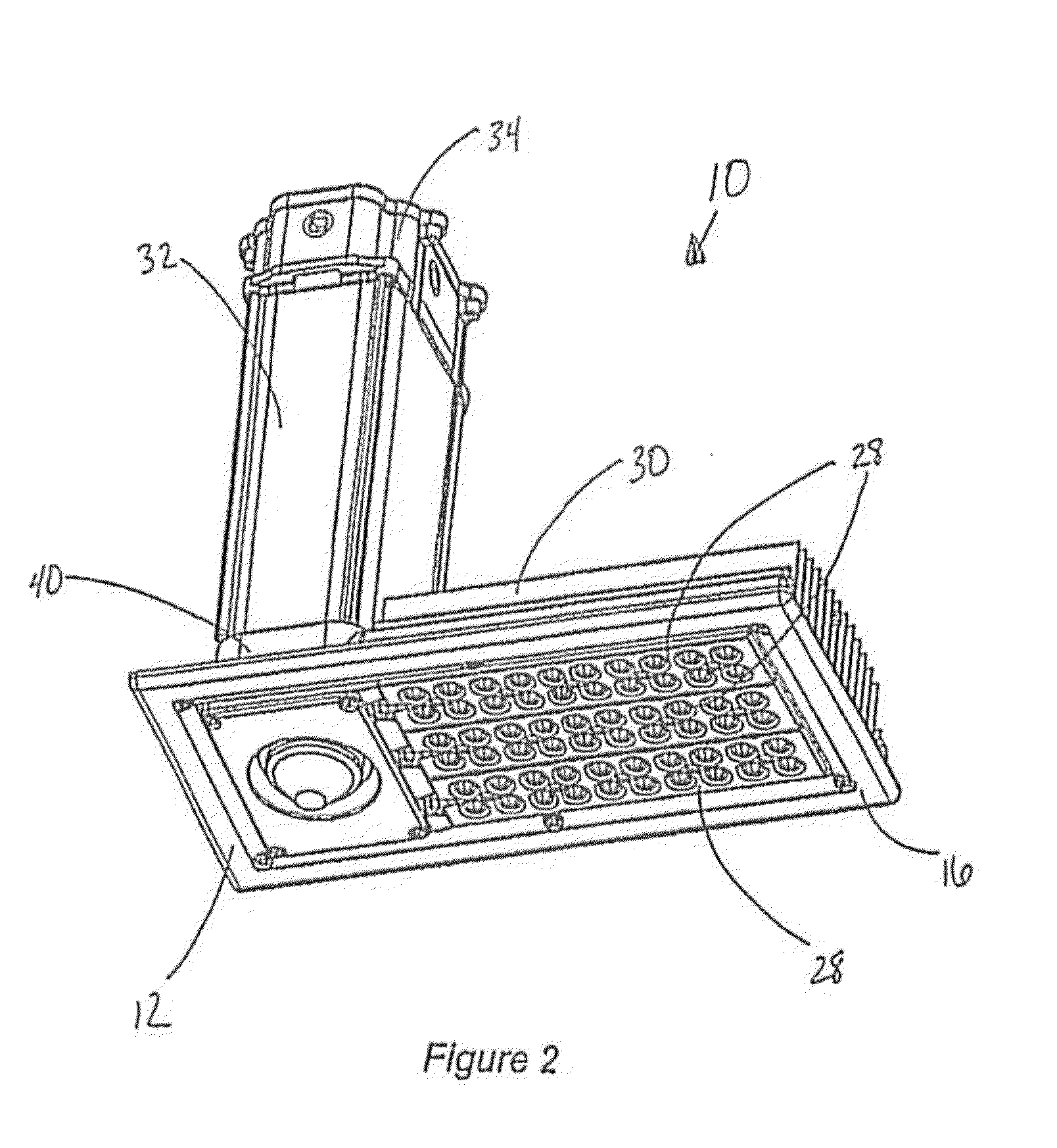
[0024]FIGS. 1-3 are perspective views of an embodiment of the inventive LED light fixture 10. Fixture 10 is installed in an overhead canopy 22 as seen in FIG. 10. Canopy 22 typically includes a canopy sheet 20 with a fixture-receiving opening 24 therethrough. Fixture 10 includes a base member 12 having a top 14, a bottom 16, and a flange 18 for engagement with canopy sheet 20 as seen in FIGS. 1-3 and 10. Base member 12 defines a pass-through opening 26.

[0025]A vertical sleeve 32 is secured at top 14 of base member 12 for alignment with pass-through opening 26 as seen in FIGS. 1-5. Vertical sleeve 32 is also secured to bottom member 40 as seen in FIG. 1. Driver-tray assembly 38 has a bottom casting 51, bottom member 40 is part of base member 12 and is engageable with bottom casting 51. Driver-tray assembly 38 includes a vertical driver-support structure 42 extends upwardly therefrom, at least one driver 44 is secured to support structure 42 and support structure 42 has upwardly-facin...


PUM


Abstract

An overhead LED light fixture including a base member with a vertical sleeve secured to the top of the base member for alignment with a pass-through opening. The fixture has a driver-tray assembly with a bottom member engageable with the base member at the pass-through opening, a vertical driver-support structure extending upwardly therefrom, at least one driver secured to the support structure, and the driver-tray assembly is slideably received within the vertical sleeve. When used as a canopy light, the driver-tray assembly is removable from below the canopy to facilitate servicing, upgrading or replacing of components.

Description

FIELD OF THE INVENTION[0001]This invention is related generally to overhead light fixtures and, more particularly, to canopy-mounted light fixtures and to methods for servicing same.BACKGROUND OF THE INVENTION[0002]In describing the overhead light fixture of this invention and its advantages, particular reference will be made to what is referred to as canopy light fixtures; however, the inventive apparatus and method is more generally applicable to overhead lighting fixtures.[0003]Canopy-mounted light fixtures (“fixtures”) are often used to provide lighting in areas such as service stations, drive-through facilities such as banks, and other outdoor lighting environments which are generally lighted from above, often high overhead. A great variety of canopy-mounted light fixtures have been developed. Some examples of such prior art fixtures are those disclosed in the following United States patents: U.S. Pat. No. 7,572,038 (Kinnune, et al.), U.S. Pat. No. 6,561,670 (Jongewaard, et al....

Claims


Application Information

Patent Timeline
IPC IPC(8): F21V21/00B23P17/00B23P6/00
CPCF21V23/006F21V23/0471F21V29/75F21V29/76F21Y2115/10F21V23/007Y10T29/4973Y10T29/49723F21S8/026F21S8/04
Inventor MILETICH, DONSTANLEY, JOHN
Owner IDEAL IND LIGHTING LLC
Why Eureka
Try Eureka