Slide valve for dry goods

a technology of slide valve and dry goods, which is applied in the field of slide valve, can solve the problems of operator cleaning the slide valve, contamination of the dispensed dry goods with metal hardware, and difficulty in cleaning the typical slide valve, so as to facilitate cleaning and/or servicing of the valve, reduce the possibility of pieces, and be easy to disassemble without tools

Inactive Publication Date: 2013-07-16
TANK HLDG CORP
View PDF8 Cites 2 Cited by
  • Summary
  • Abstract
  • Description
  • Claims
  • Application Information

AI Technical Summary

Benefits of technology

[0003]The present invention provides a slide valve that is releasably coupled to a lower or dispensing end portion of a hopper. The slide valve may be readily coupled to the hopper and decoupled from the hopper to facilitate cleaning and / or servicing of the valve. Further, the slide valve is assembled from interlocking parts so that it can be readily disassembled without tools, and to substantially limit or prevent the possibility of pieces associated with the valve (such as loose fasteners or the like) coming loose and falling into the dry bulk goods that are dispensed from the hopper.
[0019]Accordingly, the slide valve of the present invention provides a valve that is readily detached from a hopper, disassembled, reassembled, and reattached to a hopper to facilitate cleaning or servicing of the valve. The slide valve reduces or eliminates the risk of contaminating dry goods that are dispensed through the slide valve with loose pieces from the valve, and facilitates a method by which the slide valve is readily removed from a hopper and disassembled.

Problems solved by technology

However, typical slide valves can be difficult to remove and reinstall, which discourages operators from cleaning the valves on a regular basis.
In addition, typical valves are assembled using rivets, bolts, or other mechanical fasteners that are prone to breakage or loosening during operation of the hopper and slide valve, which can lead to contamination of the dispensed dry goods with metal hardware.

Method used


Image

  • Slide valve for dry goods
  • Slide valve for dry goods
  • Slide valve for dry goods

Examples


Embodiment Construction

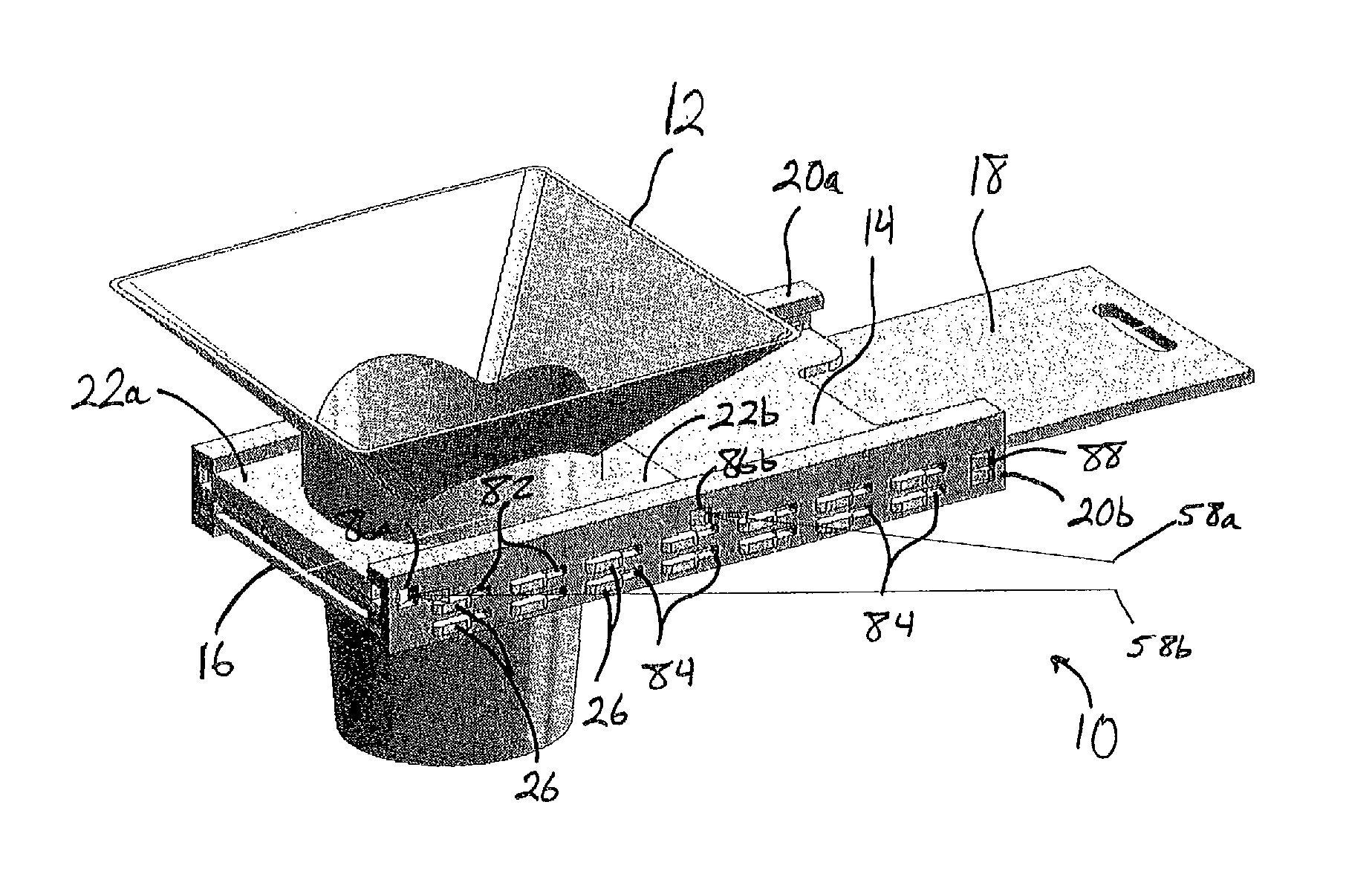
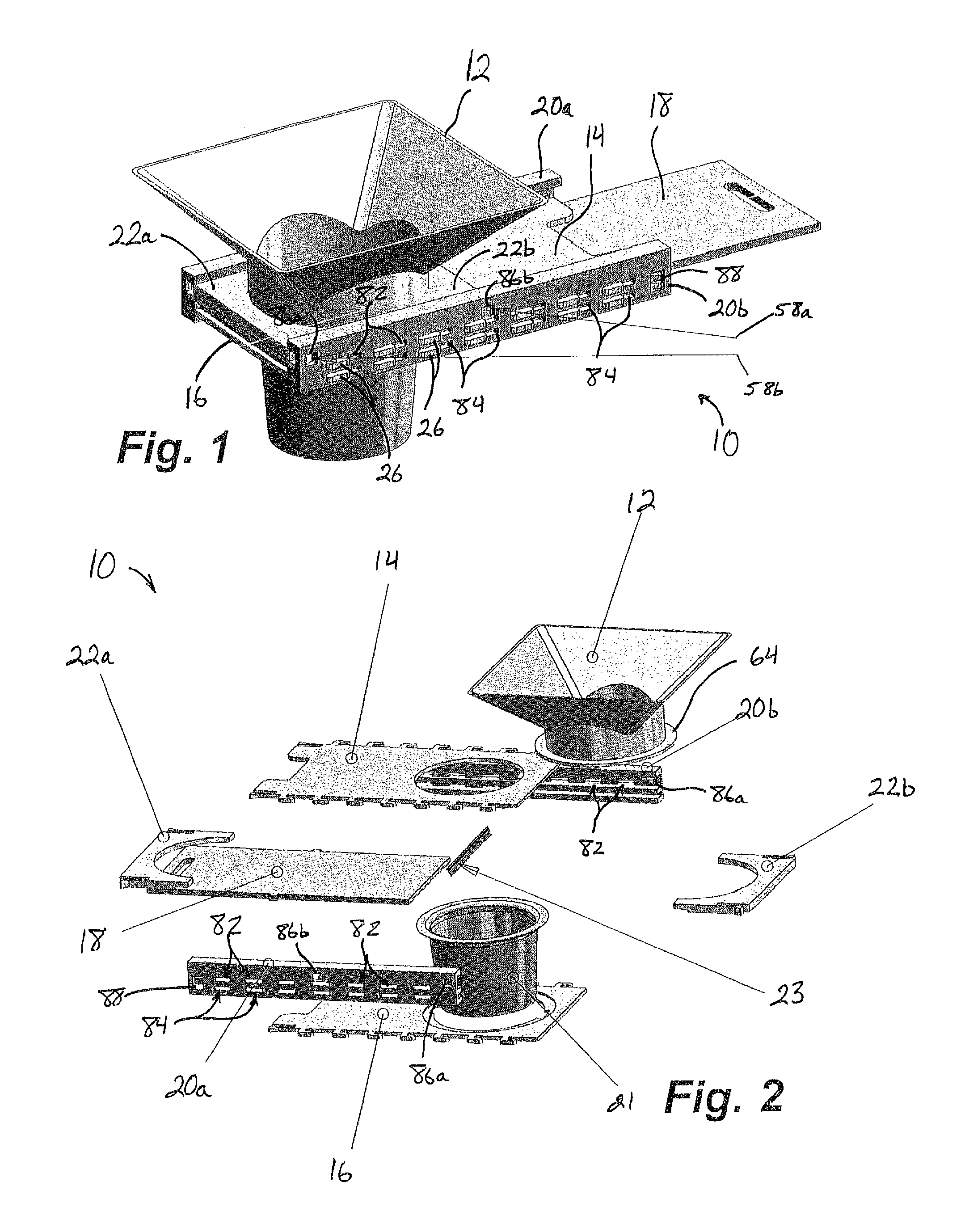
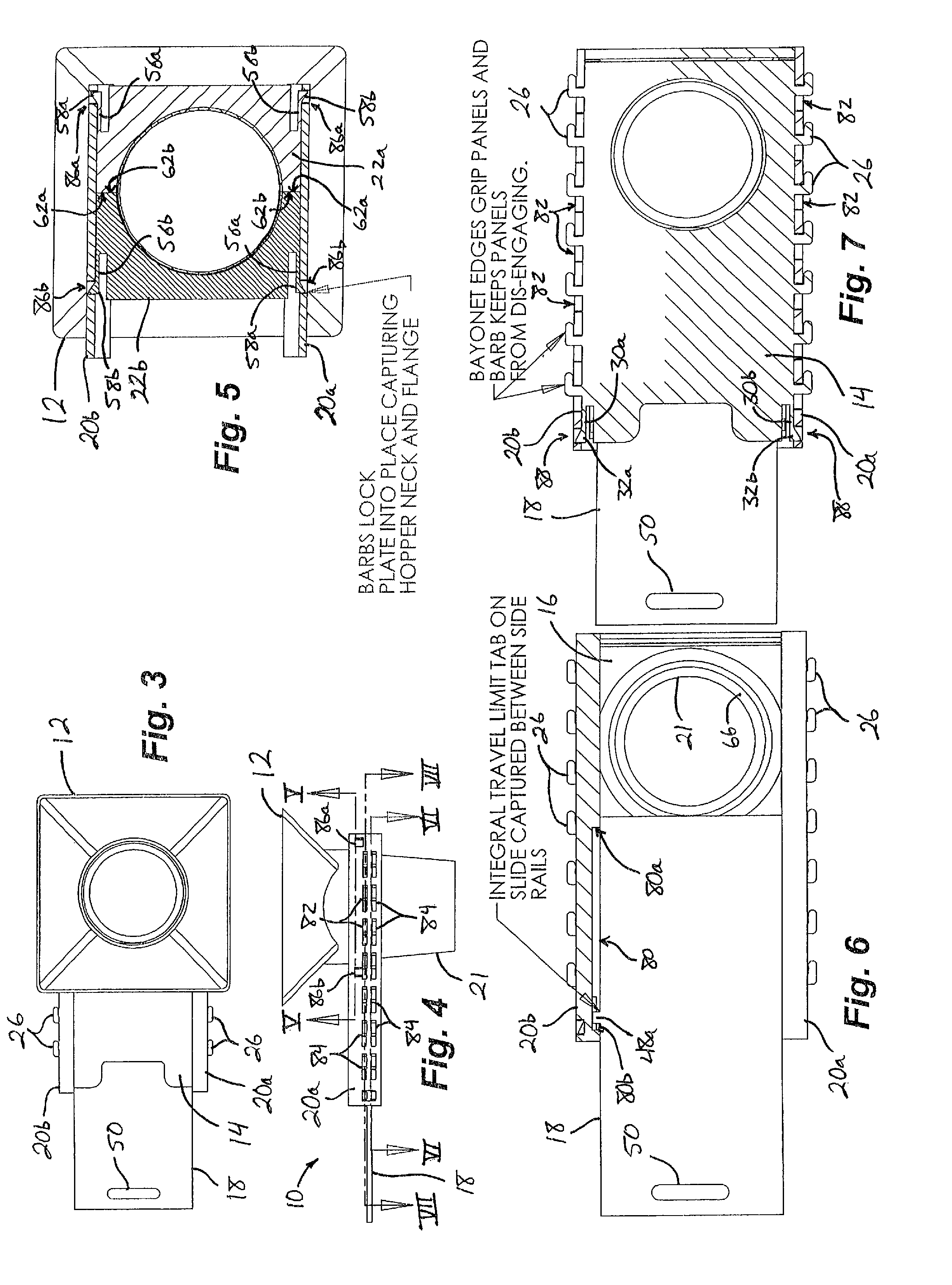
[0041]Referring now to the drawings and the illustrative embodiments depicted therein, a slide valve assembly 10 is installed at a hopper's lower dispensing portion 12 (FIG. 1). Slide valve assembly 10 includes an upper panel 14, a lower panel 16, and a movable valve panel 18, each supported between a pair of side or support rails 20a, 20b (FIGS. 1 and 2). Also supported between support rails 20a, 20b is a collar retainer made up of two collar retainer halves 22a, 22b, which are positioned above the upper panel 14 and which hold the slide valve assembly 10 to the lower end portion of the hopper 12, as will be described below. In the illustrated embodiment, an optional conduit 21 and dust seal 23 (FIG. 2) complete the slide valve assembly 10. Movable valve panel 18 is positionable between an open and extended position (FIGS. 1, 3, 4, 6-9, and 20A) and a closed and retracted position to selectively dispense dry goods out of hopper lower end portion 12 and through slide valve assembly ...


PUM

PropertyMeasurementUnit
timeaaaaaaaaaa
resilientaaaaaaaaaa
shapeaaaaaaaaaa

Abstract

A slide valve assembly is provided for selectively dispensing dry goods from a hopper. The slide valve assembly is readily attached and detached from the hopper and is readily disassembled and reassembled to facilitate cleaning and / or servicing. Preferably, the slide valve assembly includes a panel secured to spaced support rails, a movable valve panel for opening and closing of the dispensing portion of the hopper, and a collar retainer for releasable attachment to the dispensing portion of a hopper. The slide valve assembly may be attached, detached, assembled, and disassembled substantially without the use of tools or separate fasteners, to minimize the risk of creating a contamination hazard for the goods dispensed from the hopper, while still allowing for secure attachment to the hopper.

Description

FIELD OF THE INVENTION[0001]The present invention is directed to a slide valve and, more specifically, to a slide valve for use in selectively dispensing dry goods from a hopper.BACKGROUND OF THE INVENTION[0002]Hoppers are frequently used for storage and dispensing of dry goods ranging from foodstuffs to chemicals, including powders and granular materials such as plastic resins, gravel, and sand, and are provided with a dispensing valve at the bottom of the hopper to control or limit the flow of the goods out of the hopper. However, typical slide valves can be difficult to remove and reinstall, which discourages operators from cleaning the valves on a regular basis. In addition, typical valves are assembled using rivets, bolts, or other mechanical fasteners that are prone to breakage or loosening during operation of the hopper and slide valve, which can lead to contamination of the dispensed dry goods with metal hardware.SUMMARY OF THE INVENTION[0003]The present invention provides a...

Claims


Application Information

Patent Timeline
Patent Type & Authority Patents(United States)
IPC IPC(8): B65D47/00B23P19/10
CPCB65D90/587Y10T29/49815
Inventor RAZ, RICHARD
Owner TANK HLDG CORP
Why Eureka
Try Eureka