
Orthopaedic device and methods for its pre-assembly and assembly

a technology for orthopaedic devices and pre-assembly, which is applied in the field of orthopaedic devices, can solve problems such as increasing and achieve the effect of reducing the workload of surgical sta

Active Publication Date: 2013-10-17
ZIMMER SPINE INC
View PDF15 Cites 40 Cited by
  • Summary
  • Abstract
  • Description
  • Claims
  • Application Information

AI Technical Summary

Benefits of technology

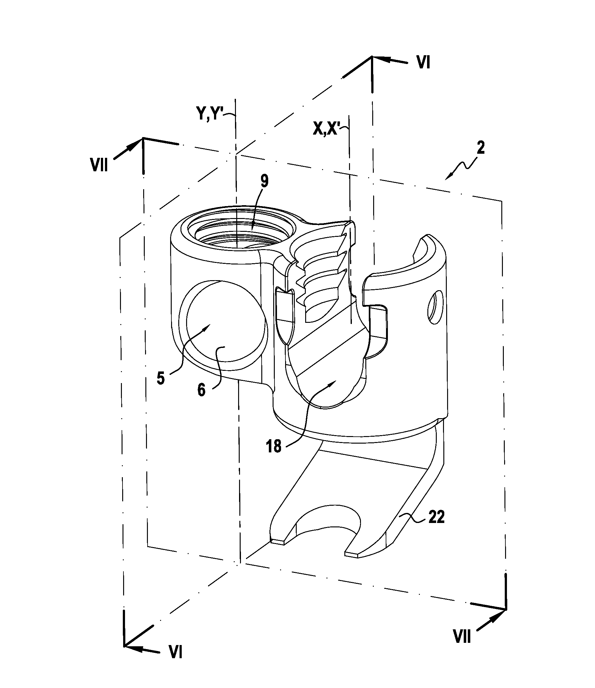
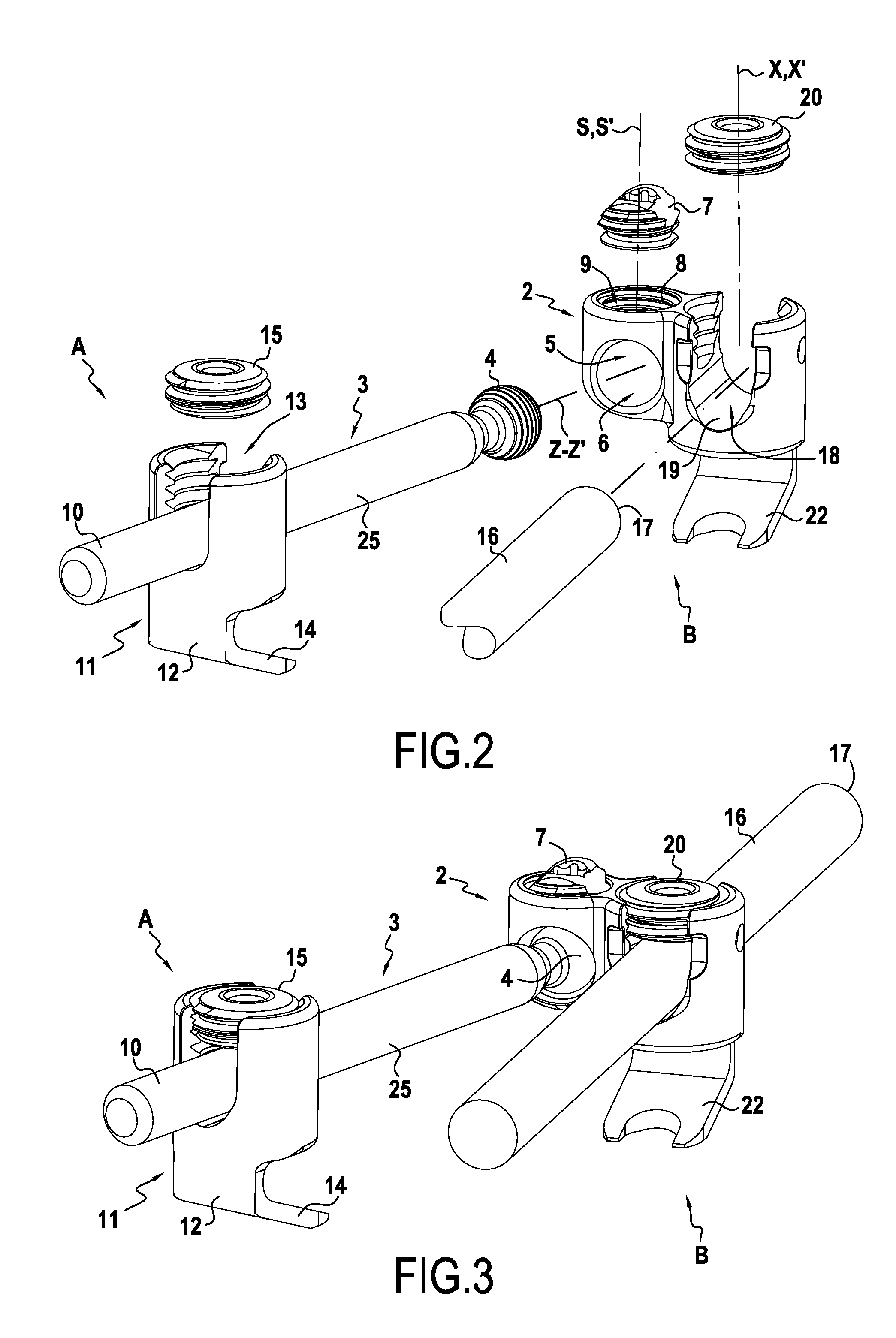
The present invention provides an orthopaedic device that reduces the surgical staff's workload. The device includes a connecting element and a lock screw. The connecting element is secured to a bone and has a lateral opening and a top opening with a screw thread. The lock screw is received within the top opening and has a screw drive accessible from outside the connecting element. The lock screw is designed to fit through the lateral opening and into the top opening to secure the first rod. The lock screw is pre-assembled to the connecting element before the introduction of the first rod to prevent accidental unscrewing. The distal end of the lock screw may be shaped to prevent it from being extracted through the top opening. The invention ensures that the lock screw cannot be easily removed from the connecting element.

Problems solved by technology

The lock screw can thus be threaded into the top opening only after the introduction of the ball-shaped rod end, and thus, when the connecting element is anchored to a bone, in the middle of the surgery operation, increasing the surgical staff's workload.

Method used


Image

  • Orthopaedic device and methods for its pre-assembly and assembly
  • Orthopaedic device and methods for its pre-assembly and assembly
  • Orthopaedic device and methods for its pre-assembly and assembly

Examples


Embodiment Construction

[0038]For the following defined terms, these definitions shall be applied, unless a different definition is given in the claims or elsewhere in this specification.

[0039]As used in this specification and the appended claims, the singular forms “a”, “an”, and “the” include plural referents unless the content clearly dictates otherwise. As used in this specification and the appended claims, the term “or” is generally employed in its sense including “and / or” unless the content clearly dictates otherwise.

[0040]The following detailed description should be read with reference to the drawings in which similar elements in different drawings are numbered the same. The detailed description and the drawings, which are not necessarily to scale, depict illustrative embodiments and are not intended to limit the scope of the invention. The illustrative embodiments depicted are intended only as exemplary. Selected features of any illustrative embodiment may be incorporated into an additional embodim...


PUM

PropertyMeasurementUnit
angleaaaaaaaaaa
angleaaaaaaaaaa
angleaaaaaaaaaa

Abstract

Orthopaedic devices including a connecting element suited for receiving at least part of a first rod, and a lock screw. The connecting element includes an anchor for securing the connecting element to a bone, in particular a vertebra, a first lateral opening, and a top opening with a first inner screw thread. The lock screw is received within the top opening and includes a proximal face presenting a screw drive, accessible from outside the connecting element, a distal end for locking the first rod within the connecting element, and wherein the lock screw is adapted to fit through the first lateral opening to be subsequently introduced into the top opening with the proximal face leading.

Description

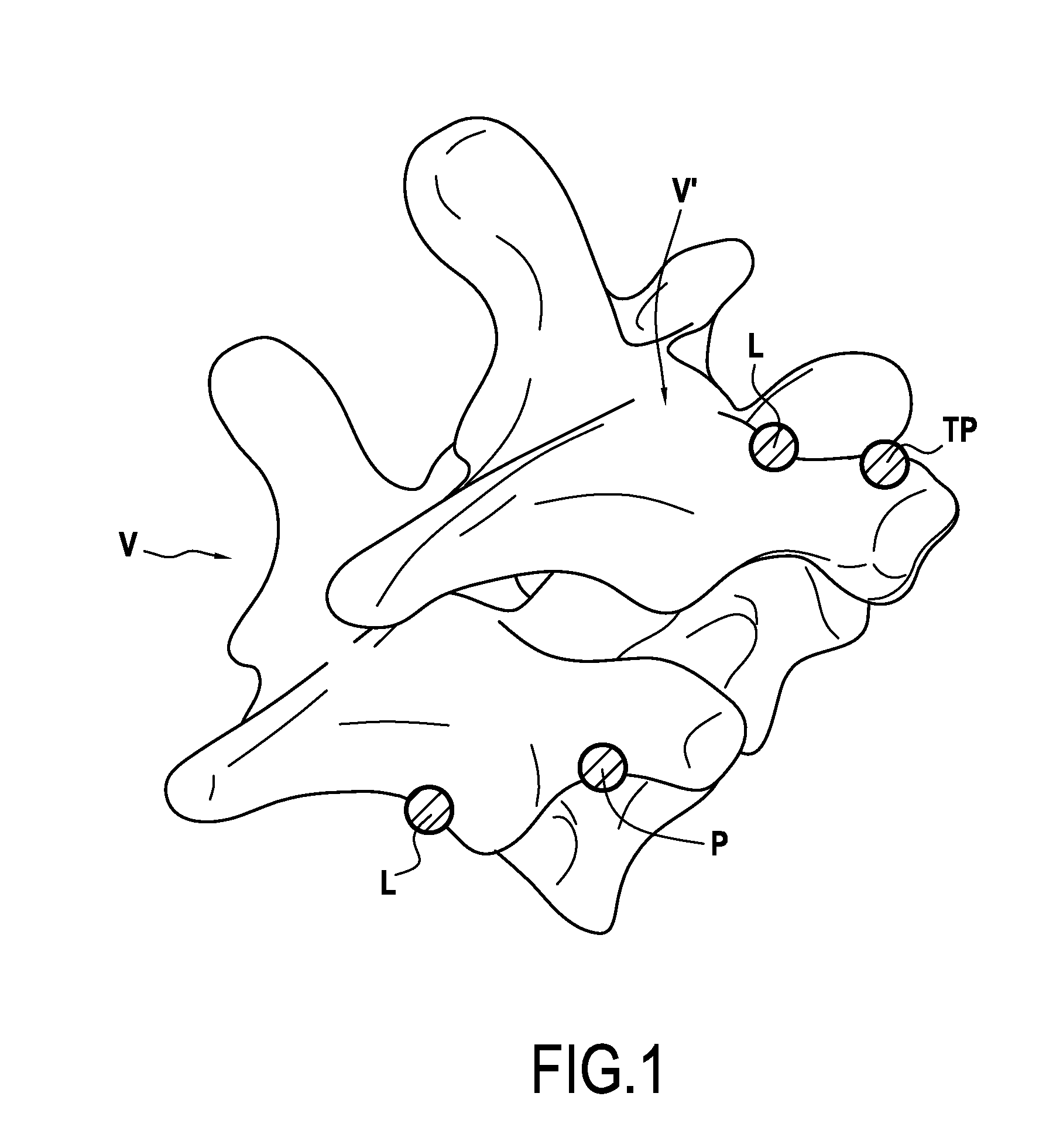
CROSS-REFERENCE TO RELATED APPLICATIONS[0001]This application is a continuation of PCT / EP2011 / 072806 filed on Dec. 14, 2011, which claims priority to EP10306466.3, filed on Dec. 21, 2010, the entire disclosures of which are incorporated herein by reference.TECHNICAL FIELD[0002]The presently disclosed systems, devices and methods relate to an orthopaedic device and in particular to an orthopaedic device suitable to be secured to a bone. One field of application for this orthopaedic device is holding bones in a relative position, for example, to aid in the healing of breaks or the positioning of bones, or the treatment of scoliosis, or otherwise to correct abnormal curvatures of the spine.BACKGROUND[0003]The spine is formed of superposed vertebrae, normally aligned along a vertebral axis from the lumbar vertebrae to the cervical vertebrae, each having a posterior wall from which projects a spinous process and two lateral edges from the walls of which project ribs and / or transverse pro...

Claims


Application Information

Patent Timeline
Patent Type & Authority Applications(United States)
IPC IPC(8): A61B17/70
CPCA61B17/705A61B17/7056A61B17/7005A61B17/7007A61B17/7037A61B17/704Y10T29/49963
Inventor LARROQUE-LAHITETTE, GILLESLEGALLOIS, GEORGESICHELMANN, BRUNO
Owner ZIMMER SPINE INC
Learn More