
Wellsite control employing three-dimensional imaging

a three-dimensional imaging and well-site control technology, applied in the direction of instruments, manufacturing tools, borehole/well accessories, etc., can solve the problems of difficult to know exactly where all the equipment is, difficult to apply, and complex system

Active Publication Date: 2013-10-17
NABORS DRILLING TECH USA INC
View PDF13 Cites 89 Cited by
  • Summary
  • Abstract
  • Description
  • Claims
  • Application Information

AI Technical Summary

Benefits of technology

The patent text describes a system and method for controlling drilling rigs and wellsite equipment using three-dimensional imaging and positioning technology. The system uses a variety of sensors and cameras to identify the position of equipment and the height of pipe or tubular in relation to the rig floor. This information is then used to guide and position the equipment, ensuring that it does not run into each other or become misaligned. The system is designed to improve safety and efficiency in drilling and wellsite operations by automating the process and reducing the need for human intervention.

Problems solved by technology

The same can be said for the traditional derrickman or, even with the advent of more automated pipe handling, there is still the need for human intervention to guide and position equipment as there has been no reliable way of knowing where pipe or tubular might be exactly.
Likewise it is always difficult to know exactly where all of the equipment is relative to each other so that different pieces of equipment do not run into each other.
Much has been done with two-dimensional (2D) vision systems, but without depth it has been almost impossible to apply in the wellsite environment because of lighting changes, air / environment changes and variable pieces of equipment that come in and out of view and make a system very complex.

Method used


Image

  • Wellsite control employing three-dimensional imaging
  • Wellsite control employing three-dimensional imaging
  • Wellsite control employing three-dimensional imaging

Examples


Embodiment Construction

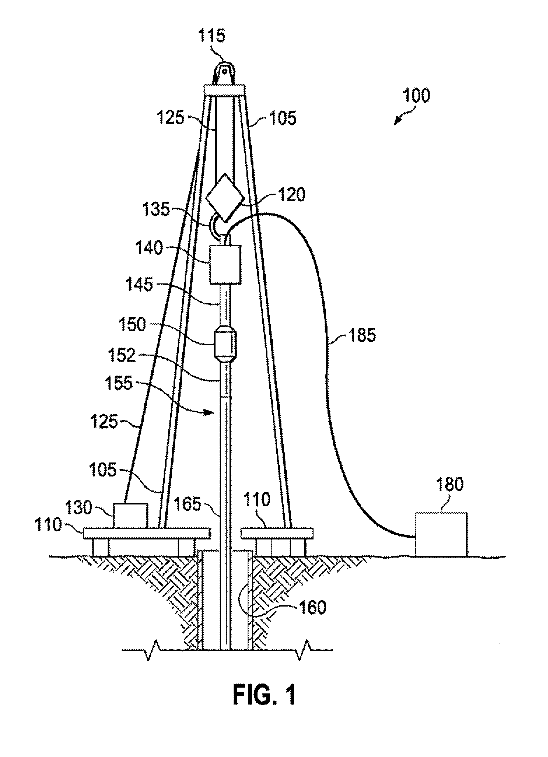
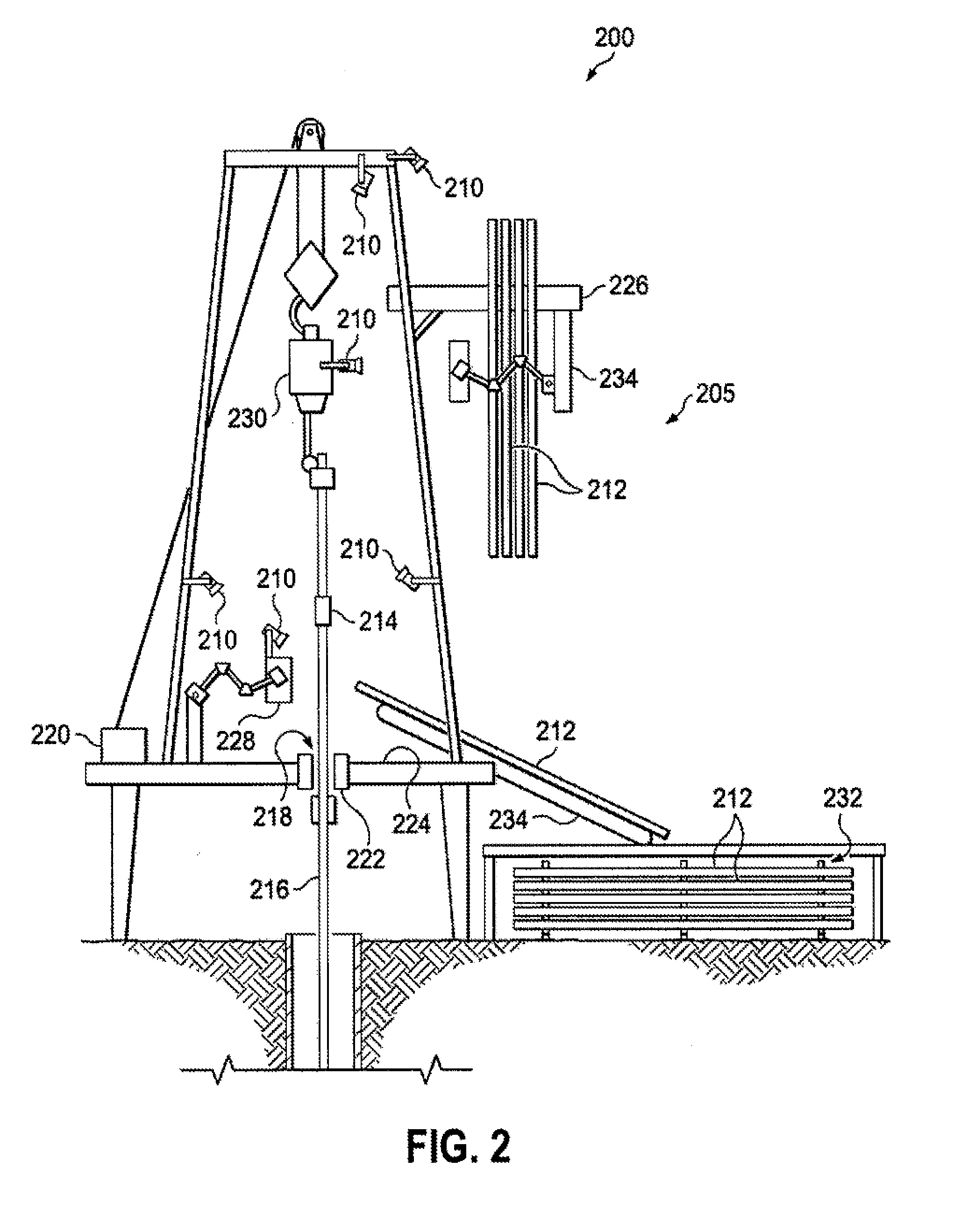
[0013]It is to be understood that the following disclosure provides many different embodiments, or examples, for implementing different features of various embodiments. Specific examples of components and arrangements are described below to simplify the present disclosure. These are, of course, merely examples and are not intended to be limiting. In addition, the present disclosure may repeat reference numerals and / or letters in the various examples. This repetition is for the purpose of simplicity and clarity and does not in itself dictate a relationship between the various embodiments and / or configurations discussed. Moreover, the formation of a first feature over or on a second feature in the description that follows may include embodiments in which the first and second features are formed in direct contact, and may also include embodiments in which additional features may be formed interposing the first and second features, such that the first and second features may not be in d...


PUM


Abstract

According to one aspect, a three-dimensional model of at least a portion of a wellsite is generated. A three-dimensional camera system is calibrated to the three-dimensional model. A draw-works encoder is calibrated. The motion of a component is monitored. The draw-works encoder is recalibrated based on the monitoring. According to another aspect, three-dimensional imaging data sets are received, the three-dimensional imaging data sets being associated with a control volume in which the portion of the wellsite is disposed. A predefined three-dimensional model is augmented with the three-dimensional imaging data sets. According to another aspect, at least one three-dimensional camera employs a first three-dimensional sensing technology that is different from a second three-dimensional sensing technology employed by at least one other three-dimensional camera. A single three-dimensional model is generated by merging respective three-dimensional imaging data sets. At least one system is controlled using the single three-dimensional model.

Description

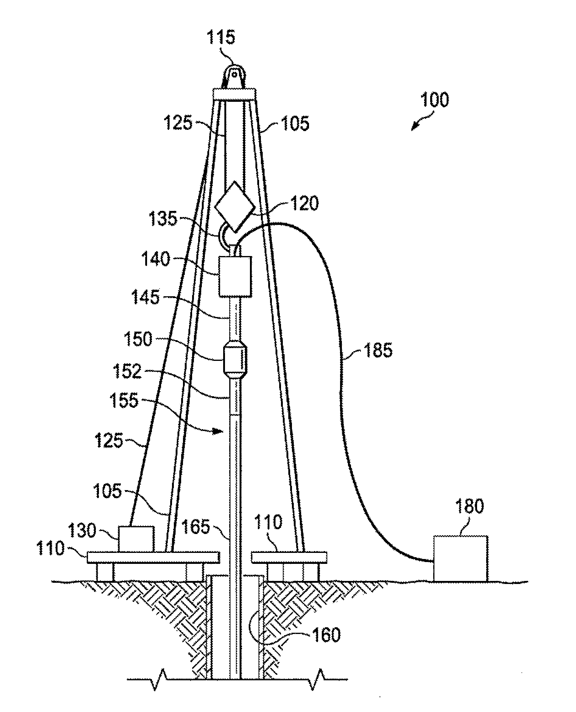
CROSS-REFERENCE TO RELATED APPLICATION[0001]This application claims the benefit of the filing date of and priority to U.S. Provisional Application No. 61 / 624,776 filed Apr. 16, 2012, entitled “Device Control Employing Three-Dimensional Imaging,” to Brian Ellis, the entire disclosure of which is hereby incorporated herein by reference.BACKGROUND OF THE DISCLOSURE[0002]Historically on drilling or service rigs, rig crews have positioned slips to set pipe in hole at a certain height, brought in tongs at the right height to latch onto tool joints (or set the height of an iron roughneck), or adjusted the height of mud buckets, pipe dopers, etc. All of this is done because the human eye is needed to identify where the height of the pipe needs to be (slip set) or where it is relative to floor and other equipment that must interact with it. The same can be said for the traditional derrickman or, even with the advent of more automated pipe handling, there is still the need for human intervent...

Claims


Application Information

Patent Timeline
Patent Type & Authority Applications(United States)
IPC IPC(8): G06F17/50
CPCG06F17/5009E21B41/00B25J19/023E21B19/00F16P3/142E21B19/20H04N13/204G06F30/20
Inventor ELLIS, BRIANANNAIYAPPA, PRADEEP
Owner NABORS DRILLING TECH USA INC
Learn More