
Hand tool

a technology of hand tools and prongs, applied in the field of hand tools, can solve problems such as severe injury or even death, and achieve the effect of increasing the frictional engagement of the prongs

Inactive Publication Date: 2013-10-24
LEE CHRISTOPHER RYAN
View PDF3 Cites 0 Cited by
  • Summary
  • Abstract
  • Description
  • Claims
  • Application Information

AI Technical Summary

Benefits of technology

The patent text describes a hand tool that has a removable or permanent connection between the handle and tool head. The permanent connection is stronger and more durable for tough work conditions. Additionally, the tool has a rubber strip that can be applied to the edges of the prongs to increase their grip on objects or articles. This makes the tool easier to use and more reliable for use in tough work environments.

Problems solved by technology

In these applications, workers are exposed to static electrical discharges or current when workers make contact with equipment or electrical current, which can result in severe injury or even death.

Method used


Image

  • Hand tool
  • Hand tool
  • Hand tool

Examples


Embodiment Construction

[0058]The term “about” as used herein refers to a quantity, level, value, dimension, size, or amount that varies to some extent based on the context in which it is used. For example, such variation can be by as much as 5%. At the least, each numerical parameter can be construed in light of the number of reported significant digits and by applying ordinary rounding techniques.

[0059]Any number range recited herein relating to any physical feature, such as dimension, size, or thickness, are to be understood to include any integer within the recited range, unless otherwise indicated.

[0060]It should be understood that the terms “a” and “an” as used above and elsewhere herein refer to “one or more” of the enumerated components. It will be clear to one of ordinary skill in the art that the use of the singular includes the plural unless specifically stated otherwise. Therefore, the terms “a,”“an” and “at least one” are used interchangeably in this application.

[0061]Unless otherwise indicate...


PUM


Abstract

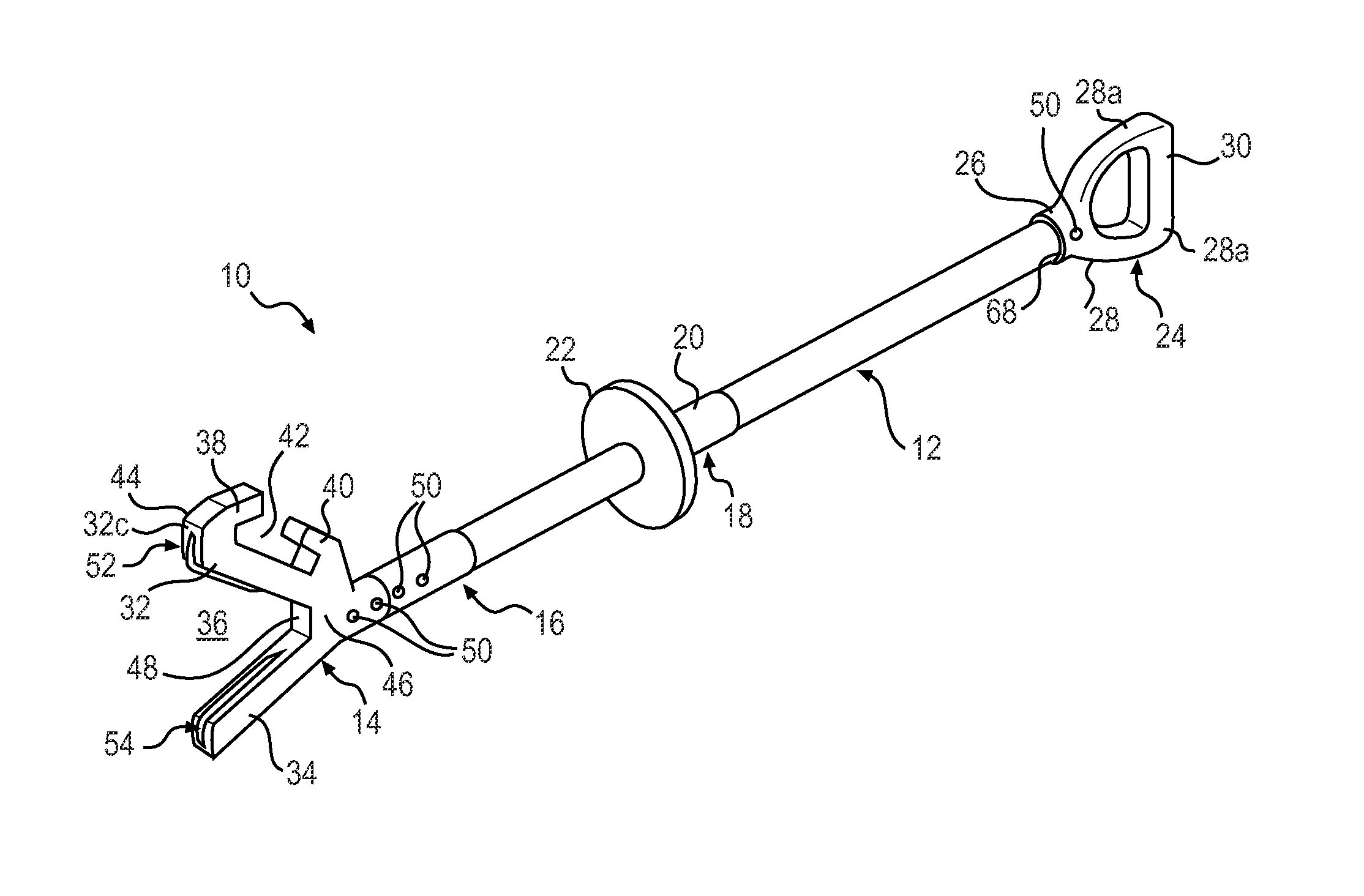
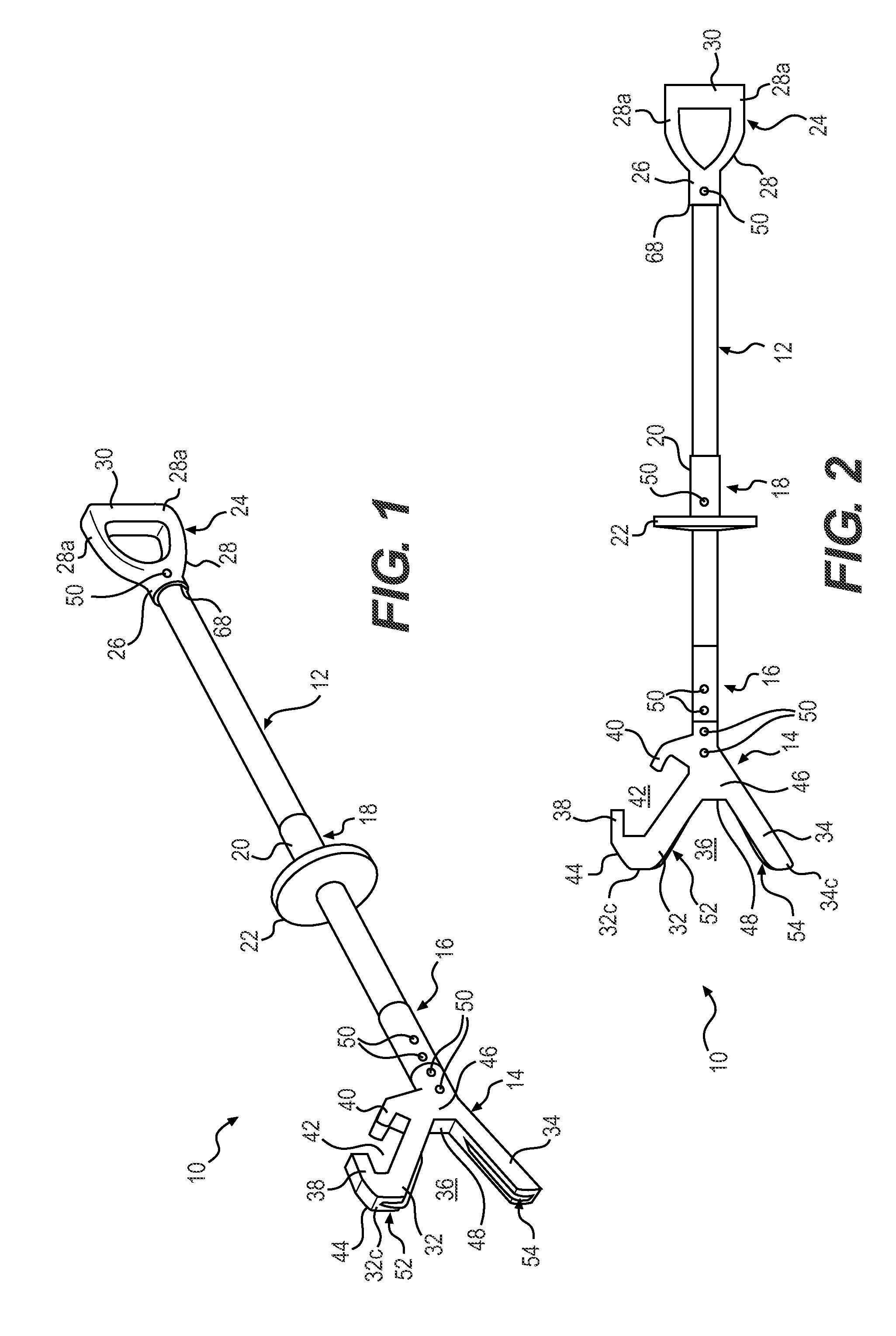
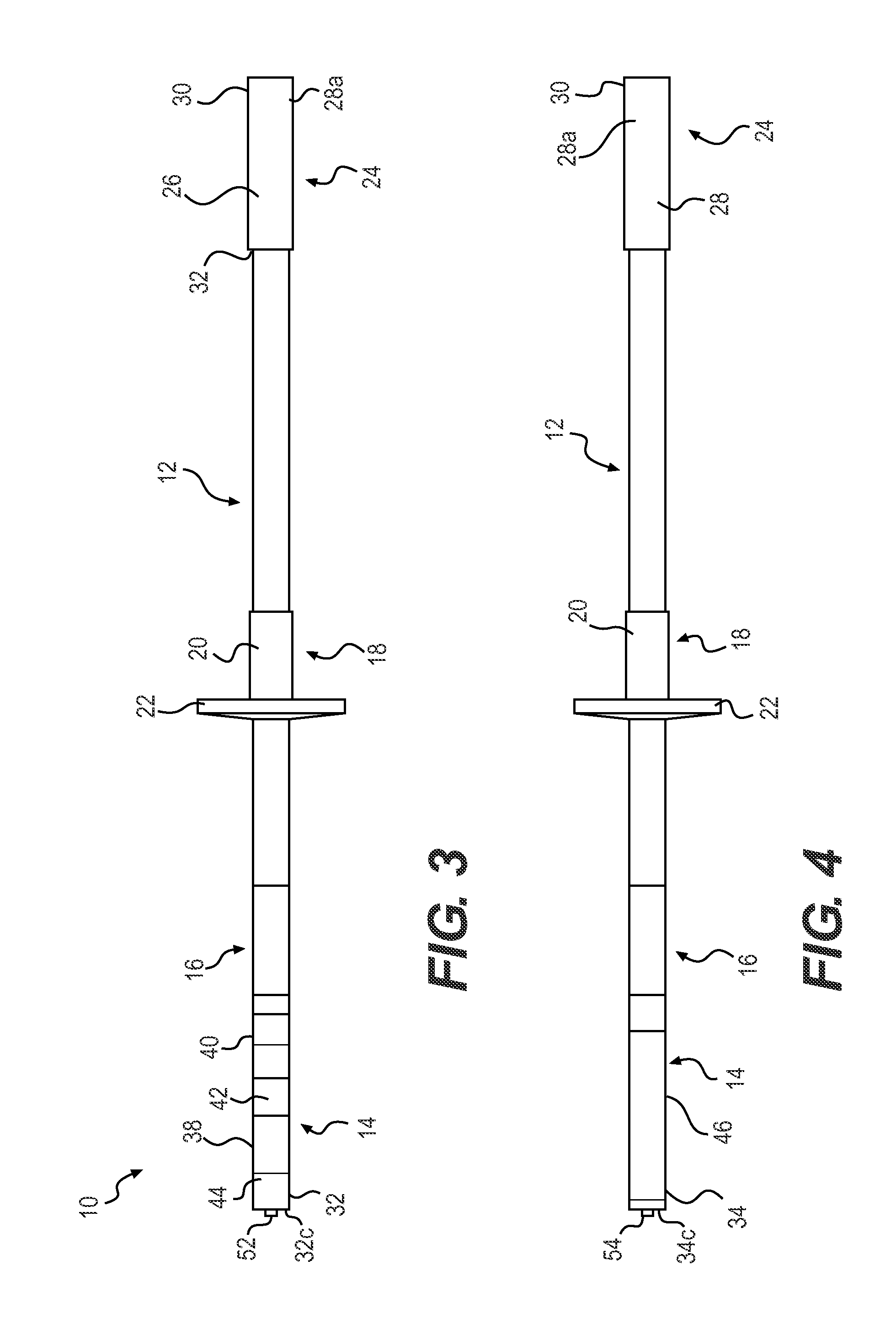
A hand tool including a handle and a tool head. The tool head is a V-shaped or modified V-shaped tool head.

Description

RELATED APPLICATIONS[0001]This is a Continuation application filed under 35 U.S.C. 120 as a continuation of U.S. patent application Ser. No. 13 / 450,839, with the filing date of Apr. 19, 2012, the entire content of which is hereby incorporated by reference in its entirety.FIELD[0002]A hand tool for multiple uses and applications, in particular for pushing, pulling, gripping, and / or manipulating objects or articles by a user. The hand tool includes a V-shaped or modified V-shaped tool head provided with one or more gripping or manipulating prongs and / or hooks.BACKGROUND[0003]There exists a need for a hand tool for pushing, pulling, gripping and / or manipulating objects. In particular, workers in a commercial or industrial setting often need a hand tool when working, for example, on an offshore oil rig, handling electrical power equipment, or when conducting manufacturing and maintenance operations. The uses for such a hand tool include pushing against surfaces, edges or corners of boxe...

Claims


Application Information

Patent Timeline
Patent Type & Authority Applications(United States)
IPC IPC(8): B25J1/04
CPCB25J1/04
Inventor LEE, CHRISTOPHER RYAN
Owner LEE CHRISTOPHER RYAN
Learn More