High efficiency, high performance metal-organic framework (MOF) membranes in hollow fibers and tubular modules

Active Publication Date: 2016-06-30
GEORGIA TECH RES CORP
View PDF0 Cites 4 Cited by
  • Summary
  • Abstract
  • Description
  • Claims
  • Application Information

AI Technical Summary

Benefits of technology

[0009]Zeolite and MOF membranes are typically synthesized in a reactor, and then removed for washing and mounting in a separate module. However, in this invention, the inventors demonstrate an in situ flow process to synthesize a membrane on or inside hollow fiber and tubular modules at a controlled location, and to subsequently activate the membrane and measure separation properties in situ without having to remove the membrane. Furthermore, damage to membranes during module construction and handling are elimi

Problems solved by technology

Despite their performance limitations, polymeric membranes have continued to dominate industrial membrane separations due to their relative ease of processing into morphologies such as hollow fibers.4 The greatest scientific challenge facing molecular sieving membranes is the lack of an easily scalable, reliable, and benign fabrication process.5 This limitation has been particularly severe for zeolite membranes, which are typically fabricated by hydrothermal synthesis on high-cost support materials.
It has been

Method used


Image

  • High efficiency, high performance metal-organic framework (MOF) membranes in hollow fibers and tubular modules
  • High efficiency, high performance metal-organic framework (MOF) membranes in hollow fibers and tubular modules
  • High efficiency, high performance metal-organic framework (MOF) membranes in hollow fibers and tubular modules

Examples


example 1

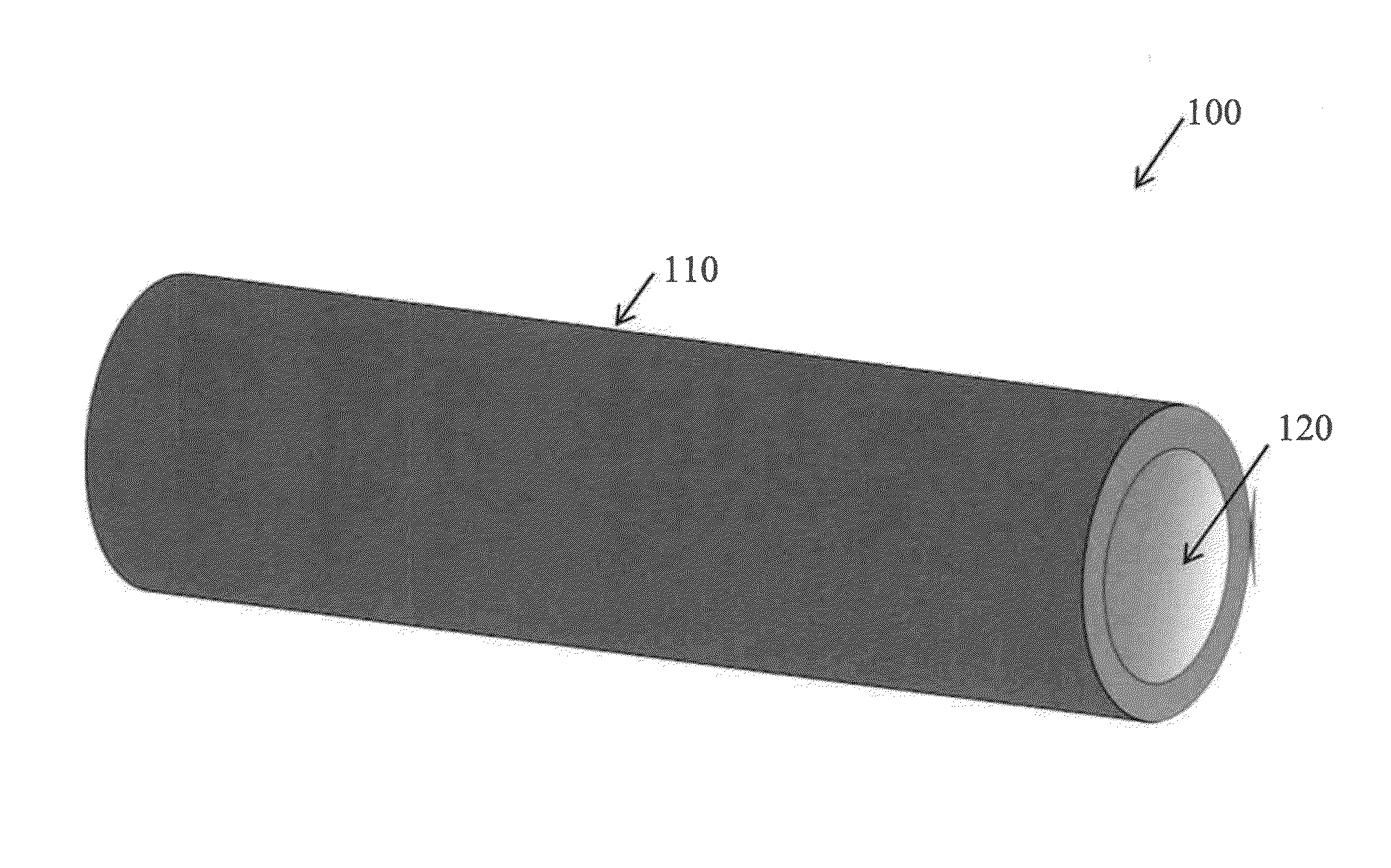
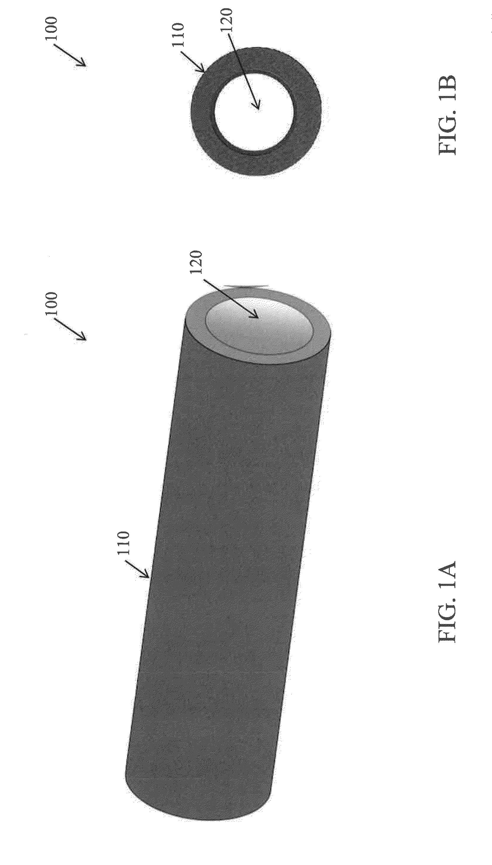
[0169]First, about 10 mL of neat 1-octanol solvent was flowed through a bore 110 using a syringe pump.

[0170]Second, about 3 mL of a Zn+2 / 1-octanol solution containing 0.11 g Zinc nitrate hexahydrate (Zn+2) in about 40 mL 1-octanol (about 0.018 mol / L) was flowed through the bore 110 of a horizontal hollow fiber 100 at a flow rate of about 10 μL / hour. In an embodiment, a limited Zn+2 / 1-octanol solution containing about 0.005 mol / L to about 0.1 mol / L Zn+2 in 1-octanol may be used. In an embodiment, a limited Zn+2 / 1-octanol solution containing about 0.01 mol / L to about 0.03 mol / L Zn+2 in 1-octanol may be used. Increasing the Zn+2 concentration to about 0.03 mol / L leads to reduction of the membrane thickness and increase in crystal nucleation.

[0171]About 70 mL of an aqueous mIm solution containing about 9 g mIm in about 80 mL dionized water (DI) (about 1.37 mol / L) was slowly poured into the reactor module 400, immersing the outer (shell) side surface 105 of the hollow fiber 100. In an em...

example 2

[0175]First, about 10 mL DI was first flowed through the bore 110 followed by about 3 mL of an aqueous Zn+2 (bore) solution (about 0.018 mol / L). About 70 mL of an aqueous mIm solution (about 1.37 mol / L) was added to the outer (shell) side surface 105 (i.e., slowly poured into the reactor module 400 and was gently stirred at about 60 rpm to prevent the formation of local concentration gradients) while the aqueous Zn+2 (bore) solution was flowed at about 10 μL / hour for about 2 hours. After about 2 hours of bore solution flow, the pump was stopped for about 3.5 hours to provide a static growth step. After about 3.5 hours, the pump was continued for about 20 minutes. After about 20 minutes, the pump was stopped for another 3.5 hours to provide another static growth step.

[0176]To stop the reaction, about 20 mL DI was flowed through the bore 110 while the outer (shell) side surface 105 was soaked in about 70 mL of neat DI (and replaced three times) to remove the excess Zn+2. Then, about 2...

example 3

[0177]First, about 10 mL 1-octanol was first flowed through the bore 110 followed by about 3 mL of a Zn+2 / 1-octanol (bore) solution (about 0.018 mol / L). About 70 mL of an mIm / 1-octanol solution (about 1.37 mol / L) was added to the outer (shell) side surface 105 while the Zn+2 / 1-octanol (bore) solution was flowed at about 10 μL / hour for about 2 hours. After about 2 hours of bore solution flow, the pump was stopped for about 3.5 hours to provide a static growth step. After about 3.5 hours, the pump was continued for about 20 minutes. After about 20 minutes, the pump was stopped for another 3.5 hours to provide another static growth step.

[0178]To stop the reaction, about 10 mL neat 1-octanol solvent was pushed through the bore 110 while the outer (shell) side surface 105 was soaked in about 70 mL of neat 1-octanol solvent. Then, about 10 mL of heptanes were pushed through the bore 110 while the outer (shell) side surface 105 was soaked in about 70 mL of heptanes to remove the 1-octanol....


PUM

PropertyMeasurementUnit
Temperatureaaaaaaaaaa
Fractionaaaaaaaaaa

Abstract

A reactor cell for measuring gas and liquid permeation is disclosed. A hollow fiber is supported by and sealed into a first hole and a second hole of the reactor module. The first and second ends of the hollow fiber are sealed with a sealing solution. Methods for making and using the reactor cell are also disclosed. As made and used, the reactor cell further comprises a molecular sieving membrane that is uniform and free of defects grown on an inner bore surface of the hollow fiber.

Description

PRIOR RELATED APPLICATIONS[0001]The present application is a continuation-in-part of U.S. patent application Ser. No. 14 / 231,871, which claims priority to U.S. Provisional Patent Application Ser. No. 61 / 913,592, filed on Dec. 9, 2013 for “Flow Processing and Characterization of Metal-Organic Framework (MOF) Membranes in Hollow Fiber and Tubular Modules” and to U.S. Provisional Patent Application Ser. No. 61 / 820,489, filed on May 7, 2013 for “Flow Processing and Characterization of Metal-Organic Framework (MOF) Membranes in Tubular and Hollow Fiber Modules.”FEDERALLY SPONSORED RESEARCH STATEMENT[0002]Not Applicable (“N / A”)REFERENCE TO MICROFICHE APPENDIX[0003]N / AFIELD OF INVENTION[0004]This invention relates to a scalable, in situ flow-processing method to synthesize metal-organic framework (MOF) membranes on or inside hollow fiber and tubular modules and to characterize their molecular transport properties, and, in particular, to a high-efficiency, high-performance zeolitic imidazol...

Claims


Application Information

Patent Timeline
IPC IPC(8): B01J19/24C07C7/144
CPCB01J19/2415B01J2219/24C07C7/144B01D63/063B01D67/0051B01D69/08Y10T29/49345Y02P20/582
Inventor NAIR, SANKAREUM, KIWONJONES, CHRISTOPHER W.ROWNAGHI, ALI
Owner GEORGIA TECH RES CORP
Why Eureka
Try Eureka