Tray, ink jet textile printing apparatus, storing method of tray, and manufacturing method of printed matter

Active Publication Date: 2013-10-24
SEIKO EPSON CORP
View PDF6 Cites 11 Cited by
  • Summary
  • Abstract
  • Description
  • Claims
  • Application Information

AI Technical Summary

Benefits of technology

[0038]According to the aspect of the invention, it is possible to obtain the same effect as

Problems solved by technology

However, as described above, when a long shaft fixed positioning portion is provided in the tray, it is difficult to horizontally place the tray because the tray is disturbed by the long shaft portion even when attempting to place the tray on a flat table by detaching the tray from the support unit since the long shaft portion is in the way.
In addition, it is actually difficult to perform setting wo

Method used


Image

  • Tray, ink jet textile printing apparatus, storing method of tray, and manufacturing method of printed matter
  • Tray, ink jet textile printing apparatus, storing method of tray, and manufacturing method of printed matter
  • Tray, ink jet textile printing apparatus, storing method of tray, and manufacturing method of printed matter

Examples


Example

First Embodiment

Referencing FIGS. 3 to 7

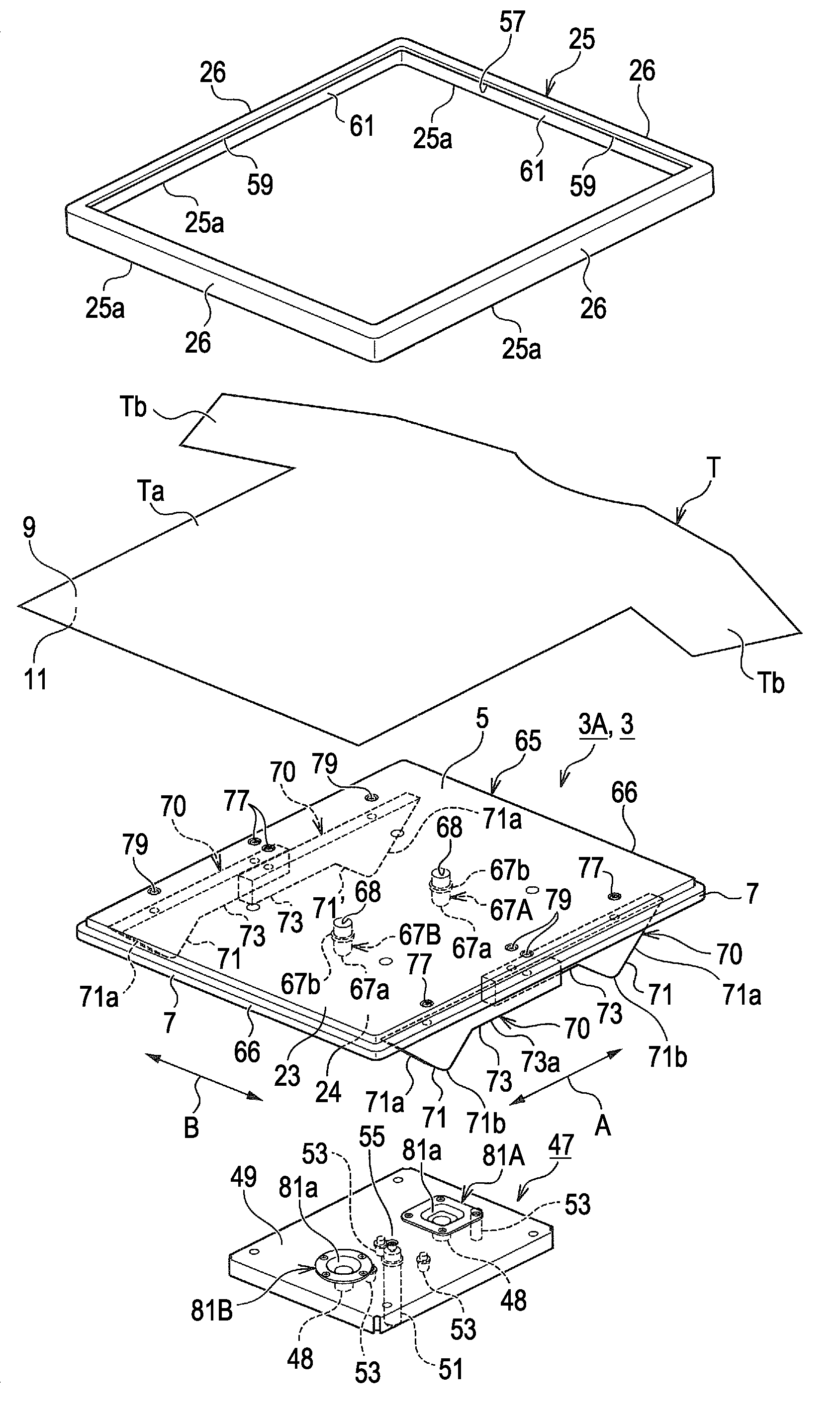
[0060]A tray 3A according to a first embodiment (hereinafter, described as trays 3A, 3B, and 3C, respectively when classifying each of embodiments 1 to 3) includes a main body 65 which has a setting surface 23 on which the material to be printed T is set. As a first protrusion portion, the tray 3A also includes a positioning pin 67 is provided in a protruding manner at a mounting surface 24, which is the opposite side to the setting surface 23 of the main body 65. The positioning pin is used when mounting the main body 65 to the support unit 31. The tray 3A also includes a leg portion 71 which is provided in a protruding manner on the mounting surface 24 of the main body 65, and which leg portion 71 has a protruding dimension that is longer than the positioning pin 67.

[0061]That is, the tray 3A includes the leg portion 71 which horizontally supports the main body 65 in a state in which a tip end 67a of the positioning pin 67 does not come into...

Example

Second Embodiment

Refer to FIGS. 8 and 9

[0113]In a tray 3B according to a second embodiment, only a part of configurations in a main body 65 is different from the tray 3A according to the first embodiment, and other configurations than that are the same as those in the first embodiment.

[0114]Accordingly, here, descriptions of the same configurations as those in the first embodiment are omitted. A configuration of the tray 3B according to the second embodiment, a form of use, and the operation which are executed when using the tray 3B will be described mainly based on the configuration of the main body 65 which is different from that in the first embodiment.

[0115]That is, according to the embodiment, as illustrated in FIG. 8, four concave portions 87 (at which a leg portion 71 of another tray 3B which is accumulated on the tray 3B is arranged) are formed corresponding to the number of leg portions 71 and positions on a setting surface 23 of the main body 65. Here, it is preferable tha...

Example

Third Embodiment

Refer to FIG. 10

[0120]In a tray 3C according to a third embodiment, configurations of a main body 65, a leg portion 71C (reference numeral C is attached in order to distinguish from that in first embodiment), and a grip portion 73C (reference numeral C is attached in order to distinguish from that in first embodiment) are different from the tray 3A according to the first embodiment, and other configurations than those are the same as those in the first embodiment.

[0121]Accordingly, here, descriptions of the same configurations as those in the first embodiment are omitted. A configuration of the tray 3B according to the third embodiment, and operation thereof will be described mainly based on the configurations of the main body 65, the leg portion 71C, and the grip portion 73C which are different from those in the first embodiment.

[0122]That is, according to the embodiment, as illustrated in FIG. 10, the grip portion 73C and the leg portion 71C are configured by separ...


PUM


Abstract

A tray which is provided so as to be detachable from a support unit of an ink jet textile printing apparatus, and includes a main body having a setting surface on which a material to be printed is set; a positioning pin which is provided in a protruding manner on the mounting surface on the opposite side to the setting surface of the main body, and is used when mounting the main body on the support unit; and a leg portion which is provided in a protruding manner on the mounting surface of the main body, and has a protruding dimension which is longer than the positioning pin.

Description

CROSS-REFERENCE TO RELATED APPLICATIONS[0001]The entire disclosure of Japanese Patent Application No. 2012-098463, filed Apr. 24, 2012 is expressly incorporated by reference herein.BACKGROUND[0002]1. Technical Field[0003]The present invention relates to a tray which is used when setting a fabric, that is, a material to be printed, an ink jet textile printing apparatus including the tray, and a method of manufacturing printed matter.[0004]2. Related Art[0005]In the related art, an ink jet textile printing apparatus has been developed and widely used, which prints a desired image by ejecting ink of each color from an ink ejecting head towards the surface of a material to be printed on, such as a T-shirt or a like fabric.[0006]When placing a target material (on which printing is performed) with respect to such an ink jet textile printing apparatus, a tray is used. The target material is supported by a transporting unit which can perform transporting of the target material toward a text...

Claims


Application Information

Patent Timeline
IPC IPC(8): B41J3/407
CPCB41J3/4078B41J11/06
Inventor TAKEUCHI, HIDEYUKIYANAGISHITA, KENJI
Owner SEIKO EPSON CORP
Why Eureka
Try Eureka