Vane pump

a technology of a vane and a slit, which is applied in the direction of liquid fuel engines, machines/engines, rotary piston liquid engines, etc., can solve the problems of avanes projecting upward from the rotor to retreat into the slits, delay in the rise of the pump discharge pressure,

Active Publication Date: 2013-10-24
KYB CORP
View PDF8 Cites 29 Cited by
  • Summary
  • Abstract
  • Description
  • Claims
  • Application Information

AI Technical Summary

Benefits of technology

[0004]When this type of conventional vane pump is left in a stopped condition continuously, however, gravity may cause the vanes projecting upward from the rotor to retreat into the slits. As a result, a

Problems solved by technology

When this type of conventional vane pump is left in a stopped condition continuously, however, gravity may cause the vanes projecting upward from the rotor to retreat into the slits.
As a result, a lar

Method used


Image

  • Vane pump
  • Vane pump
  • Vane pump

Examples


Embodiment Construction

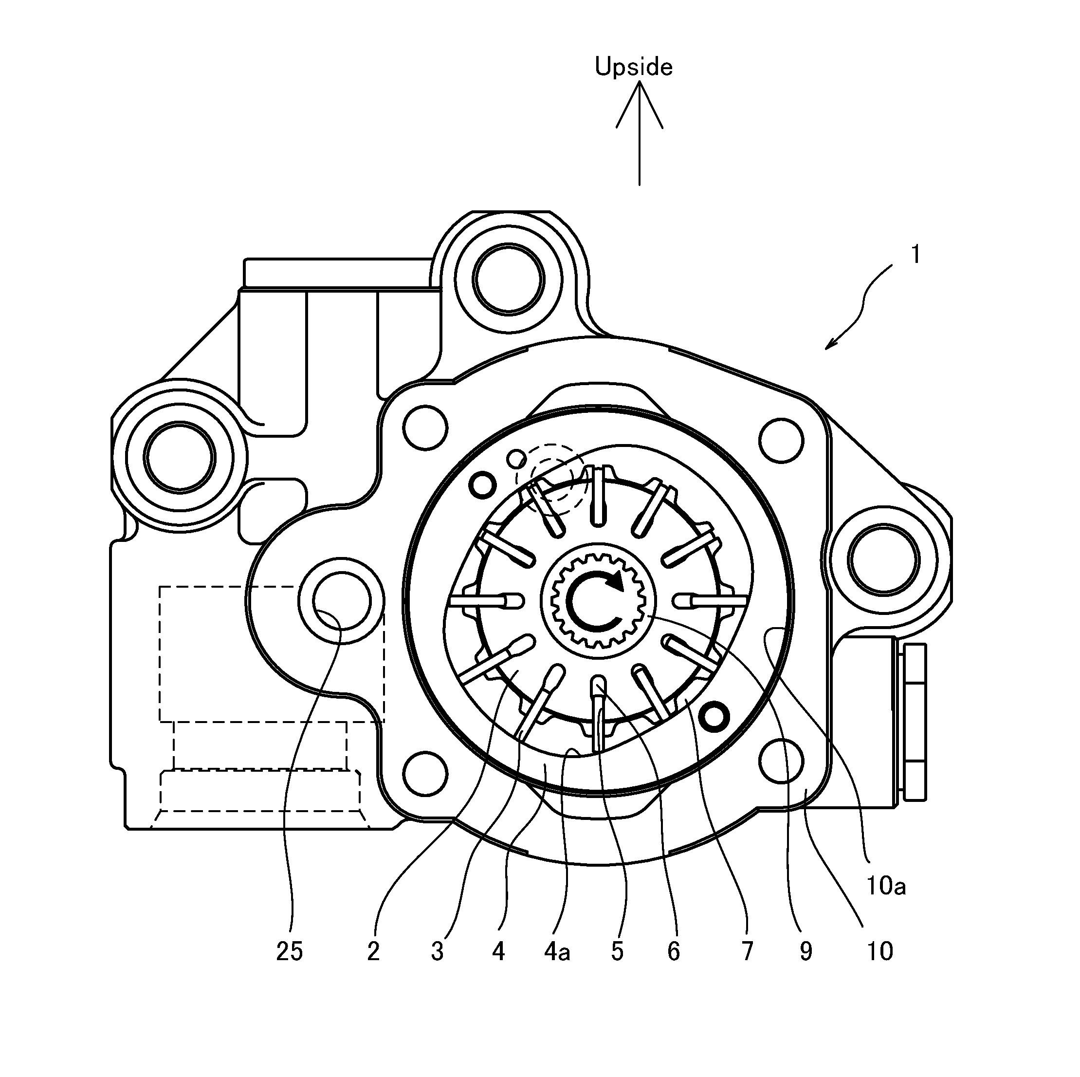
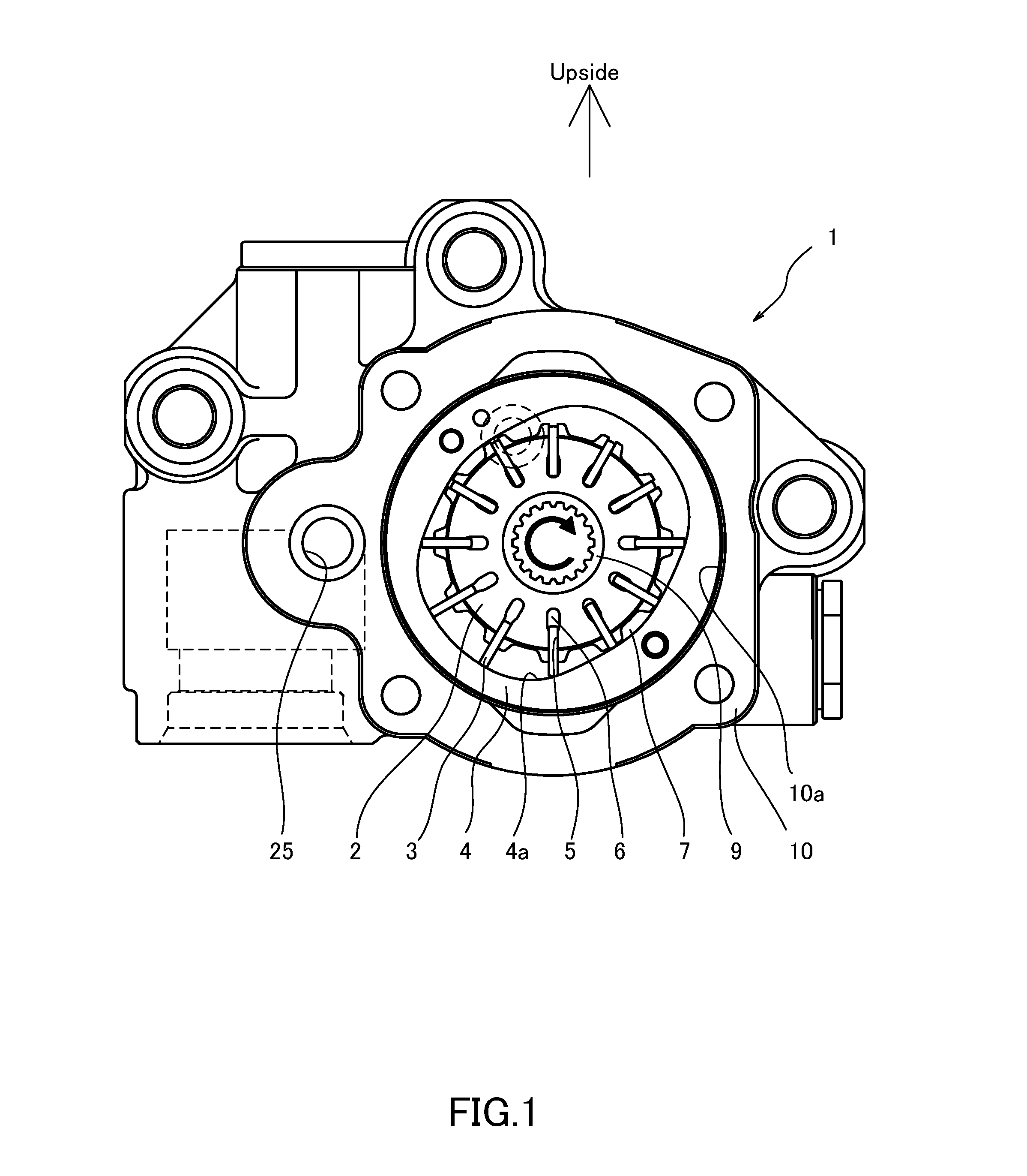
[0014]A vane pump 1 according to an embodiment of this invention will be described below with reference to the figures.

[0015]First, referring to FIG. 1, a configuration of the vane pump 1 will be described.

[0016]The vane pump 1 is used in a hydraulic device installed in a vehicle. For example, the vane pump 1 is used as an oil pressure supply source for a power steering device, a transmission, or the like.

[0017]The vane pump 1 uses working oil as a working fluid. Instead of working oil, a working fluid such as an aqueous replacement fluid, for example, may be used as the working fluid.

[0018]The vane pump 1 includes a pump body 10 formed with a pump housing recess portion 10a housing a rotor 2, a cam ring 4, a side plate 30, and so on, and a pump cover 50 that is fastened to the pump body 10 so as to seal the pump housing recess portion 10a.

[0019]In the vane pump 1, power is transmitted from an engine, not shown in the figure, to an end portion of a drive shaft 9, whereby the rotor ...


PUM


Abstract

A vane pump including a cam ring, a rotor, slits formed in the rotor, vanes inserted slidably into the slits, pump chambers defined by the vanes, back pressure chambers defined between respective base end portions of the vanes and the slits, back pressure grooves capable of communicating with the back pressure chambers as the rotor rotates, and connecting grooves connecting back pressure grooves that are adjacent in a circumferential direction of the rotor to each other, wherein a connecting groove that communicates with a back pressure groove positioned in a suction region formed above a rotary center of the rotor so as to suction a working fluid into the pump chambers is formed to have a larger passage sectional area than a connecting groove that communicates with another back pressure groove positioned in another suction region formed below the rotary center of the rotor.

Description

FIELD OF THE INVENTION[0001]This invention relates to a vane pump used as a fluid pressure supply source.BACKGROUND OF THE INVENTION[0002]In a vane pump, a plurality of vanes are housed in radial slits formed in a rotor. Each vane is biased in a projecting direction from the slit by a pressure of a back pressure chamber that presses a base end portion of the vane and a centrifugal force acting thereon as the rotor rotates, and as a result, a tip end portion of the vane slides against an inner peripheral cam surface of a cam ring. As the rotor rotates, the vane sliding against the cam surface performs a reciprocating motion such that a pump chamber expands and contracts, and as a result, working oil is supplied to and discharged from the pump chamber.[0003]JP11-230057A proposes a vane pump in which back pressure grooves communicating with a back pressure chamber and connecting grooves connecting the respective back pressure grooves are formed in front and rear pressure plates provide...

Claims


Application Information

Patent Timeline
IPC IPC(8): F04C2/00
CPCF04C2/00F01C21/0863F04C2/3446
Inventor AKATSUKA, KOICHINAIDE, RYUJI
Owner KYB CORP
Why Eureka
Try Eureka