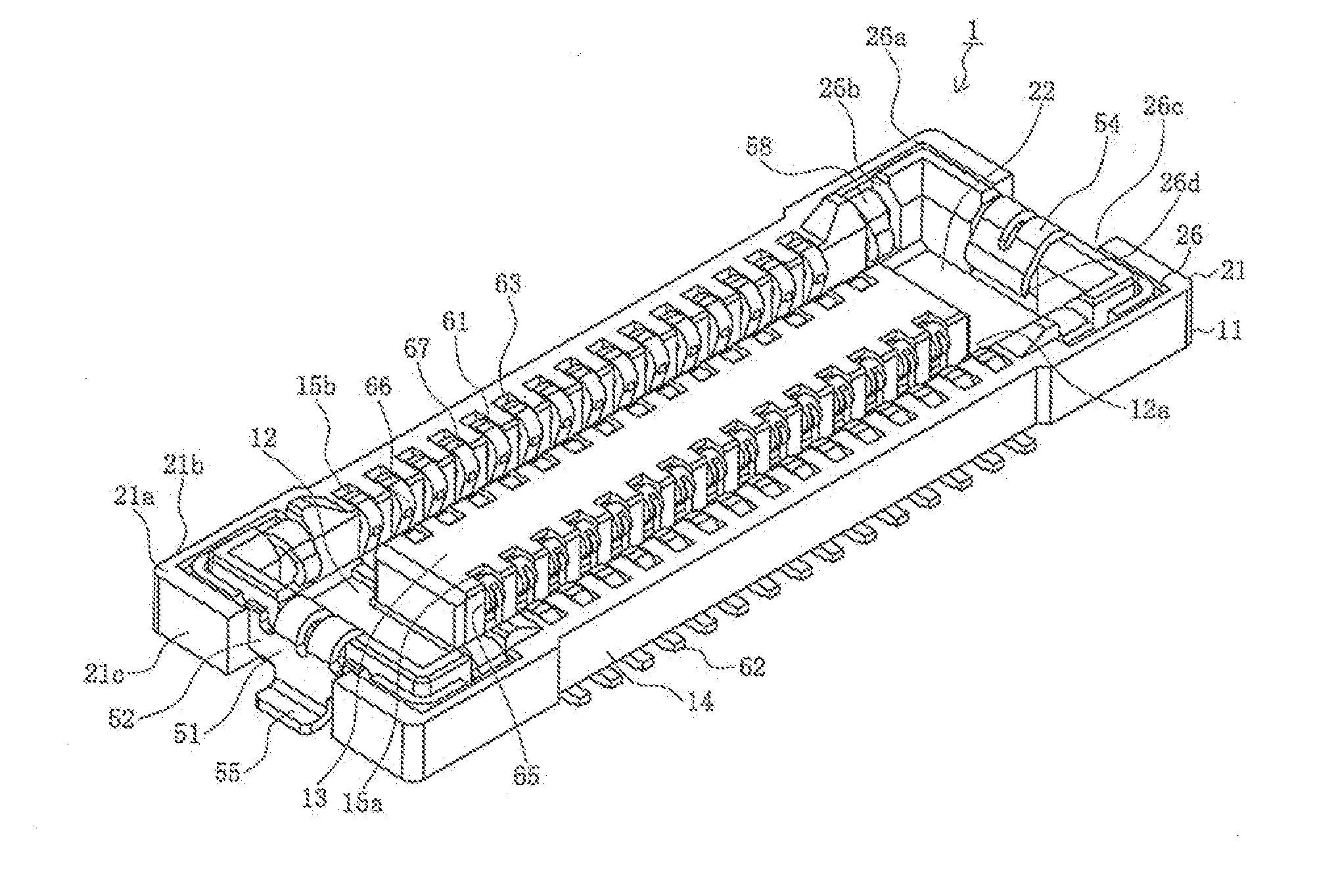
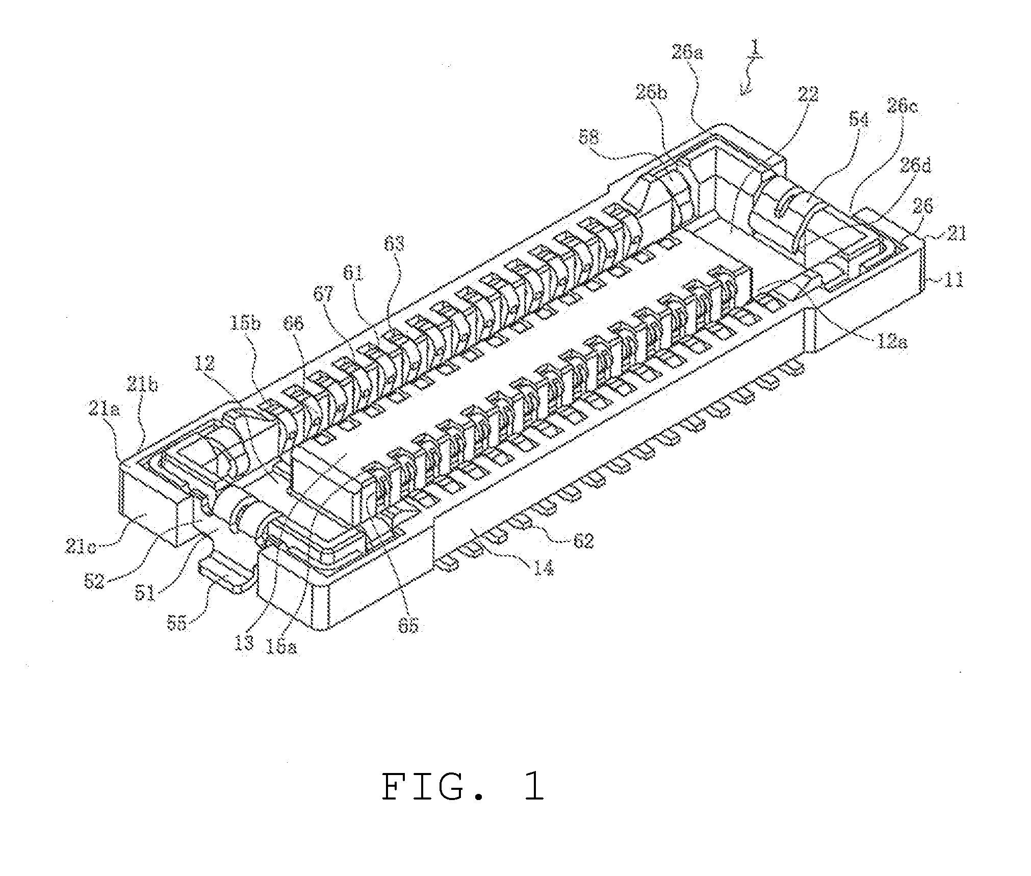
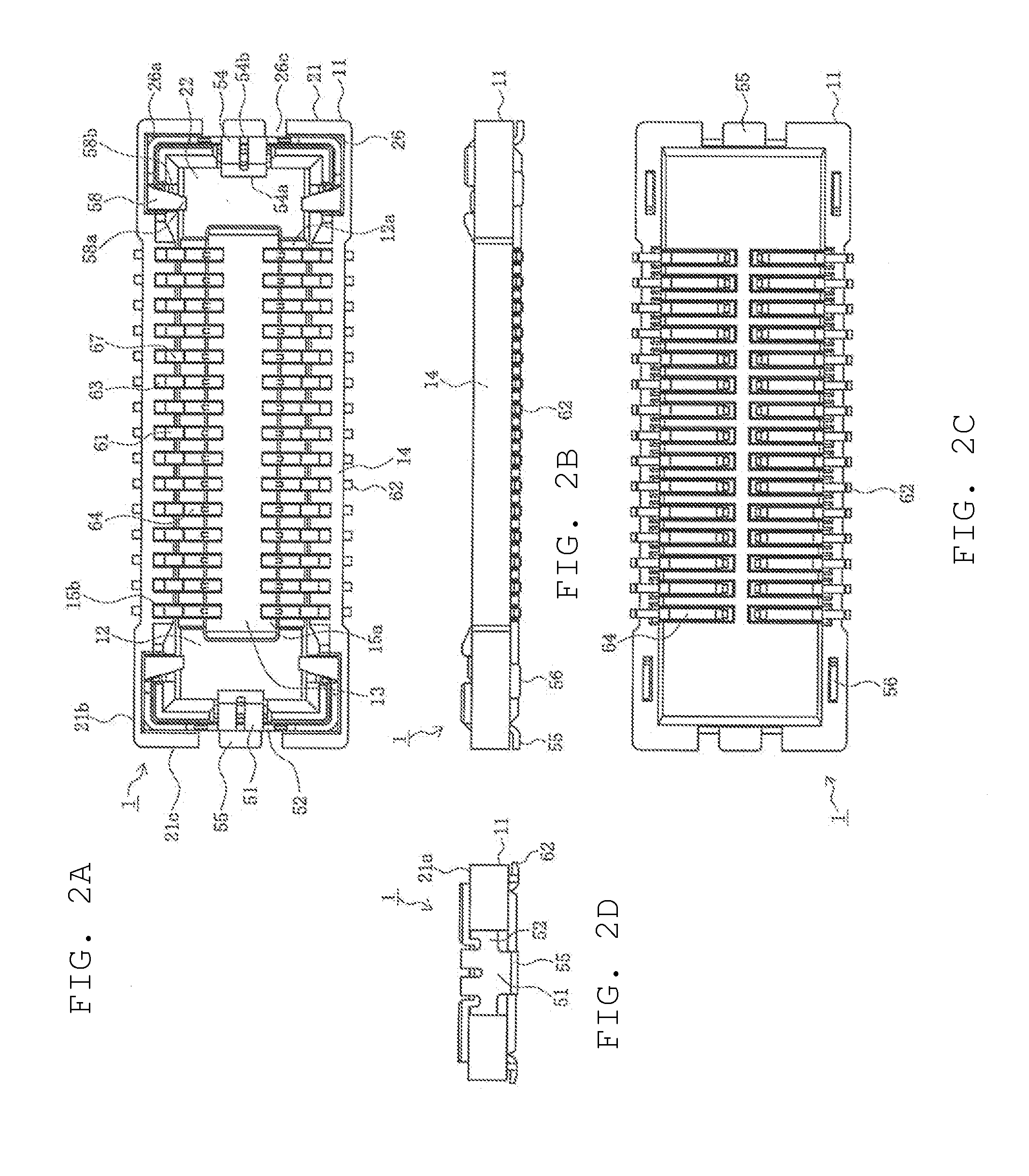
Connector

Active Publication Date: 2013-10-24
MOLEX INC
View PDF8 Cites 50 Cited by
  • Summary
  • Abstract
  • Description
  • Claims
  • Application Information

AI Technical Summary

Benefits of technology

[0014]Pursuant to the Present Disclosure, the connector is given great flexibility in the connection-arm portion of the first reinforcing metal fitting and also a wide surface area of contact is secured. Thus, the state of engagement between the first reinforcing metal fitting and the second reinforcing metal

Problems solved by technology

However, in the aforementioned conventional connector, the lateral engaging pieces 858 and central engaging piece 854, and the lateral engaging pieces 958 and central engaging piece 954 are not provided with adequate flexibility.
For this reason, there

Method used


Image

  • Connector
  • Connector
  • Connector

Examples


Embodiment Construction

[0031]While the Present Disclosure may be susceptible to embodiment in different forms, there is shown in the Figures, and will be described herein in detail, specific embodiments, with the understanding that the Present Disclosure is to be considered an exemplification of the principles of the Present Disclosure, and is not intended to limit the Present Disclosure to that as illustrated.

[0032]As such, references to a feature or aspect are intended to describe a feature or aspect of an example of the Present Disclosure, not to imply that every embodiment thereof must have the described feature or aspect. Furthermore, it should be noted that the description illustrates a number of features. While certain features have been combined together to illustrate potential system designs, those features may also be used in other combinations not expressly disclosed. Thus, the depicted combinations are not intended to be limiting, unless otherwise noted.

[0033]In the embodiments illustrated in ...


PUM


Abstract

To provide a highly reliable board-to-board connector whereby the state of engagement between the first reinforcing metal fitting and the second reinforcing metal fitting can be reliably maintained and also the state of electrical continuity between the first reinforcing metal fitting and the second reinforcing metal fitting can be reliably maintained, and thus the fit between the first connector and second connector is reliably maintained.

Description

REFERENCE TO RELATED APPLICATIONS[0001]The Present Disclosure claims priority to prior-filed Japanese Patent Application Nos. 2012-160180, entitled “Connector,” filed on 19 Jul. 2012 with the Japanese Patent Office (JPO), and 2011-226896, entitled “Connector,” filed on 14 Oct. 2011 with the JPO. The content of each of the aforementioned Patent Applications is incorporated in their entireties herein.BACKGROUND OF THE PRESENT DISCLOSURE[0002]The Present Disclosure relates, generally, to a connector, and, more particularly, to a board-to-board connector having an improved and more reliable fit.[0003]Conventionally, board-to-board connectors have been used in order to electrically connect parallel circuit boards. Such connectors are mounted to the mutually-facing surfaces of a pair of circuit boards, and engaged to achieve electrical continuity. In addition, a reinforcing metal fitting attached to each end functions as a locking member, thus maintaining the fitting with the other side o...

Claims


Application Information

Patent Timeline
IPC IPC(8): H01R12/71
CPCH01R12/712H01R12/7052H01R13/20
Inventor ONO, YASUHIRO
Owner MOLEX INC
Why Eureka
Try Eureka