System, electronic device, and charger

a technology of electronic devices and chargers, applied in the direction of battery data exchange, current supply arrangements, exchanging data chargers, etc., can solve problems such as deterioration of wireless communication quality

Inactive Publication Date: 2013-10-24
KYOCERA CORP
View PDF0 Cites 31 Cited by
  • Summary
  • Abstract
  • Description
  • Claims
  • Application Information

AI Technical Summary

Benefits of technology

[0053]According to the present invention, it is possible to provide a system, an electronic device, and a charger.

Problems solved by technology

However, when the entire charging surface generates electromagnetic waves, the electric current is also applied to coils that are not involved with charging the electronic device, thereby resulting in loss.
Electromagnetic waves also generate noise in wireless communication of the electronic device, and result in deterioration of the quality of wireless communication.

Method used


Image

  • System, electronic device, and charger
  • System, electronic device, and charger
  • System, electronic device, and charger

Examples


first embodiment

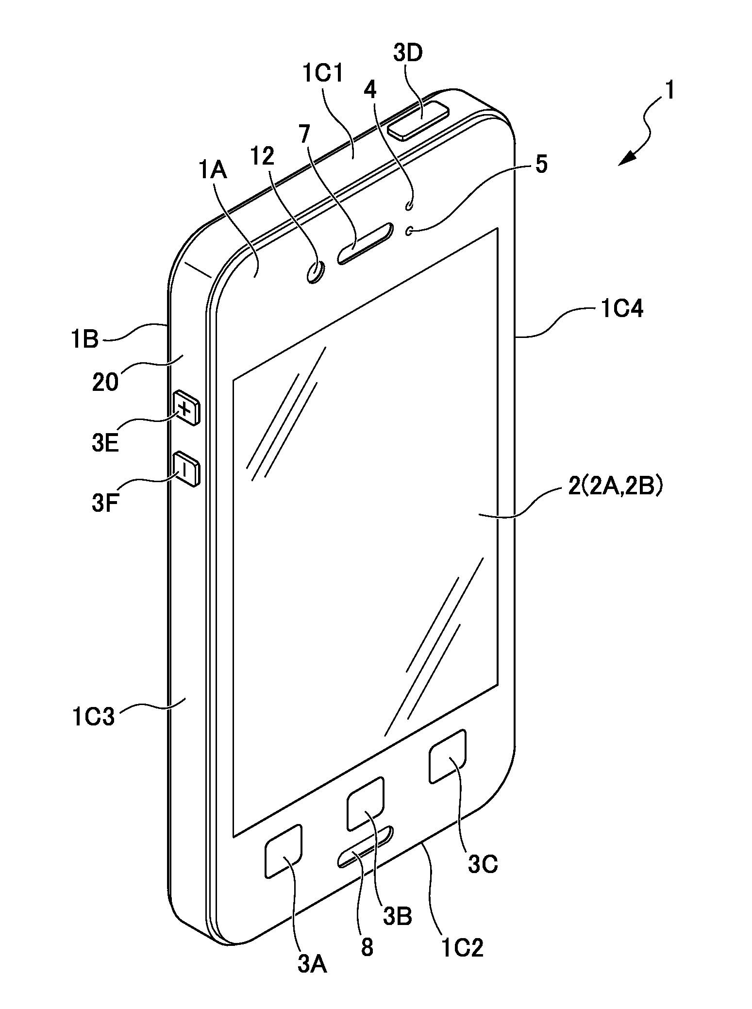
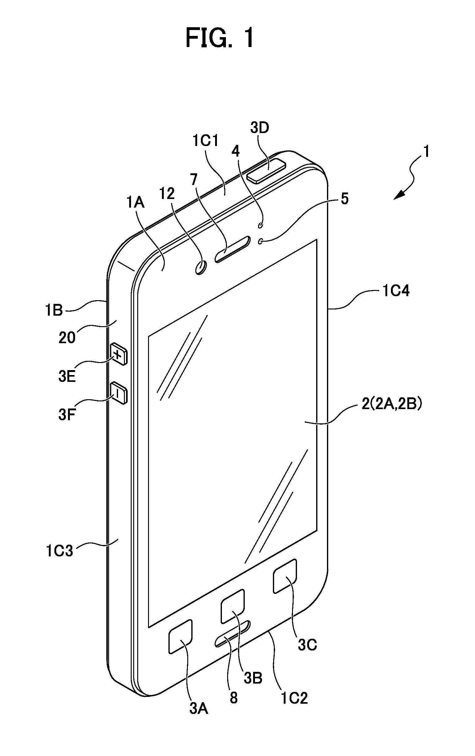
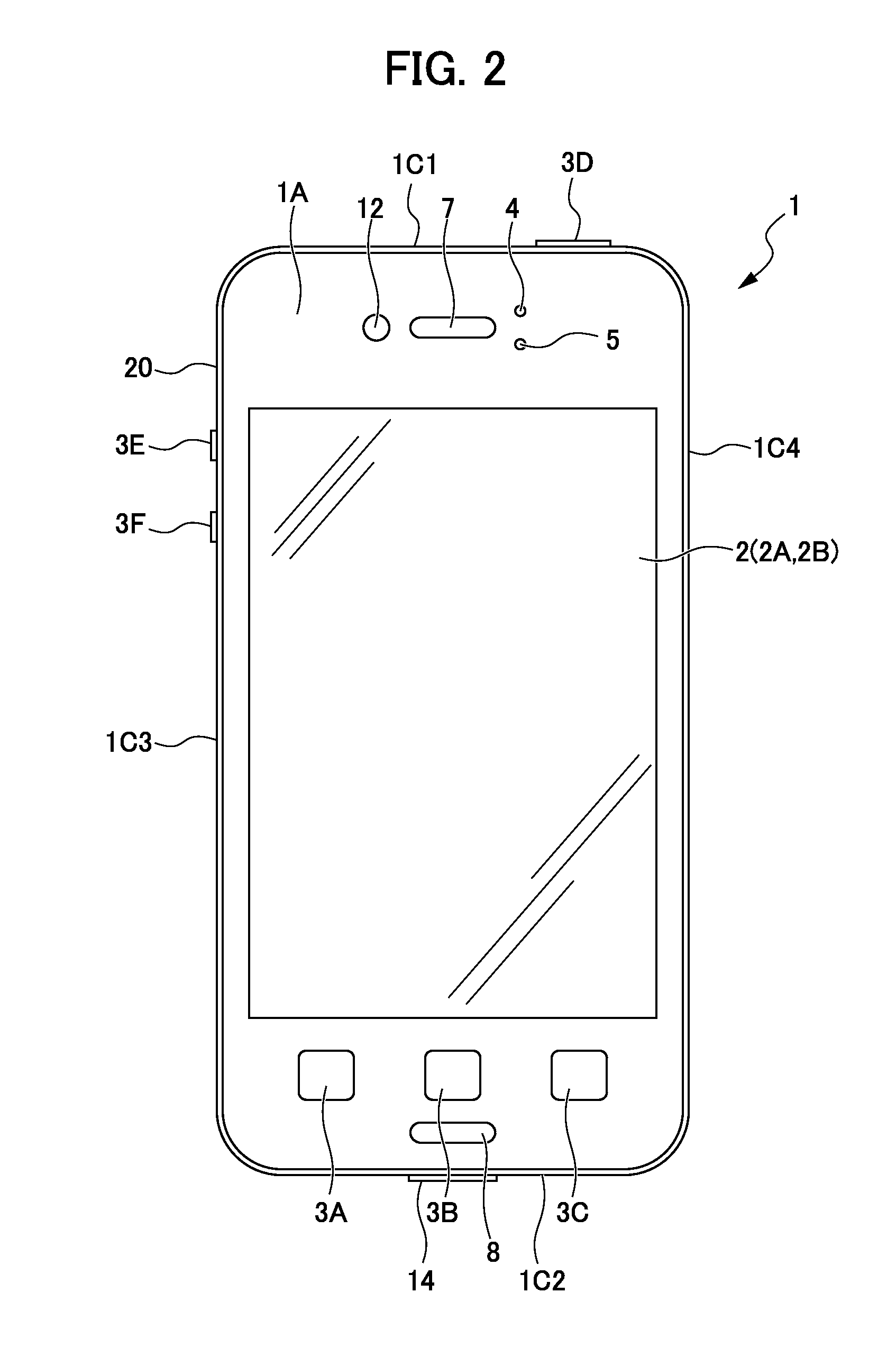
[0086]Descriptions are provided for an external appearance of a smartphone 1 that configures the system according to the embodiment with reference to FIGS. 1 to 3. As shown in FIGS. 1 to 3, the smartphone 1 has a housing 20. The housing 20 has a front face 1A, a back face 1B, and side faces 1C1 to 1C4. The front face 1A is a front face of the housing 20. The back face 1B is a back face of the housing 20. The side faces 1C1 to 1C4 are side faces that connect the front face 1A and the back face 1B. In the following descriptions, the side faces 1C1 to 1C4 may be collectively referred to as a side face 1C without specifying which face.

[0087]On the front face 1A, the smartphone 1 has a touch-screen display 2, buttons 3A to 3C, an illuminance sensor 4, a proximity sensor 5, a receiver 7, a microphone 8, and a camera 12. The smartphone 1 has a camera 13 in the back face 1B. The smartphone 1 has buttons 3D to 3F and an external interface 14 in the side face 1C. In the following descriptions...

second embodiment

[0216]As shown in FIG. 11, a system 2200 is configured by a smartphone 1 and a contactless charger 2100. The charger 2100 will be described later.

[0217]An external appearance of the smartphone 1 of the present embodiment is similar to the external appearance of the smartphone 1 shown in FIGS. 1 to 3. An example of a screen displayed on a display 2A of the smartphone 1 of the present embodiment is similar the example shown in FIG. 4.

[0218]FIG. 12 is a block diagram showing a configuration of the smartphone 1. The smartphone 1 has a touch-screen display 2, a button 3, an illuminance sensor 4, a proximity sensor 5, a communication unit 6, a receiver 7, a microphone 8, a storage 9, a controller 10, cameras 12 and 13, an external interface 14, an acceleration sensor 15, a direction sensor 16, and a rotation detection sensor 17. The configuration of the touch-screen display 2, the button 3, the illuminance sensor 4, the proximity sensor 5, the communication unit 6, the receiver 7, the mic...

third embodiment

[0272]A smartphone 1 of the present embodiment is utilized for a guidance system 3200 that is capable of guiding the smartphone 1 to a position where the power receiving efficiency is high. Descriptions are hereinafter provided for a specific configuration.

[0273]As shown in FIG. 17, the guidance system 3200 includes a charger 3100 and the smartphone 1. The guidance system 3200 has a function of executing contactless charging (wireless power feed), in which the charger 3100 wirelessly transmits power to the smartphone 1 by an electromagnetic induction scheme. The power feed scheme is not limited to the electromagnetic induction scheme, and a radio wave transmitting scheme, a resonance scheme or the like may be employed.

[0274]The charger 3100 includes a predetermined surface having a first area R. The charger 3100 transmits power through electromagnetic waves to the smartphone 1 (electronic device) that is placed on the first area R. The predetermined surface refers to a surface of th...


PUM


Abstract

A system includes a charger and a smartphone. The charger includes a plurality of coils that transmit power through electromagnetic waves. The smartphone includes a power receiving unit, a communication unit, and a storage. The power receiving unit receives power transmitted from the coils. The communication unit communicates with a base station. The storage stores information of communication quality of the communication unit with the base station, when the power receiving unit is receiving power. The smartphone selects, from among the plurality of coils, a combination of the coils for transmitting power, based on information of the communication quality stored in the storage. The charger transmits power by the coils, based on the selection by the smartphone.

Description

CROSS-REFERENCE TO RELATED APPLICATIONS[0001]This application is based on and claims the benefit of priority from Japanese Patent Application Nos. 2012-065307, 2012-068871 and 2012-069636, respectively filed on 22 Mar. 2012, 26 Mar. 2012 and 26 Mar. 2012, the contents of which are incorporated herein by reference.BACKGROUND[0002]1. Field[0003]The present invention relates to a system, an electronic device, and a charger.[0004]2. Related Art[0005]An electronic device including a touch-screen display is known technology. Examples of electronic devices include, for example, a smartphone and a tablet. The electronic device detects finger or stylus pen gestures via the touch-screen display. The electronic device is operated in accordance with the gestures thus detected.[0006]Basic operations of an electronic device including a touch-screen display are implemented by an OS (Operating System) such as Android (registered trademark), BlackBerry (registered trademark) OS, Symbian (registered ...

Claims


Application Information

Patent Timeline
Patent Type & Authority Applications(United States)
IPC IPC(8): H04B1/38
CPCH04B1/3883H04B5/0037H04M19/08H02J7/00034H02J50/402H02J50/80H02J50/90H02J50/70H02J50/10H02J50/20H02J50/12
Inventor OGATA, TAKUMIKAWASHIMA, RYOUJIITO, TAKASHI
Owner KYOCERA CORP
Why Eureka
Try Eureka