Oil skimming apparatus and method for using same

a technology of oil skimming apparatus and oil skimming capability, which is applied in the direction of sedimentation settling tank, liquid degasification, separation process, etc., can solve the problems of significant environmental mess, turbulence and splashing of liquid, etc., and achieves acceptable oil skimming capability and small and less expensive transportation

Inactive Publication Date: 2013-10-31
HORIZONTAL RENTALS
View PDF3 Cites 8 Cited by
  • Summary
  • Abstract
  • Description
  • Claims
  • Application Information

AI Technical Summary

Problems solved by technology

Normally, residual gases are still entrapped in the liquid portion and when the liquid is directed into the first settling tank, there is considerable turbulence and splashing of the liquid.
Because the liquid is directed into the top of the first settling tank, and because there are slugs of entrapped gas, normally significant environmental mess is created at the first tank.

Method used


Image

  • Oil skimming apparatus and method for using same
  • Oil skimming apparatus and method for using same
  • Oil skimming apparatus and method for using same

Examples


Embodiment Construction

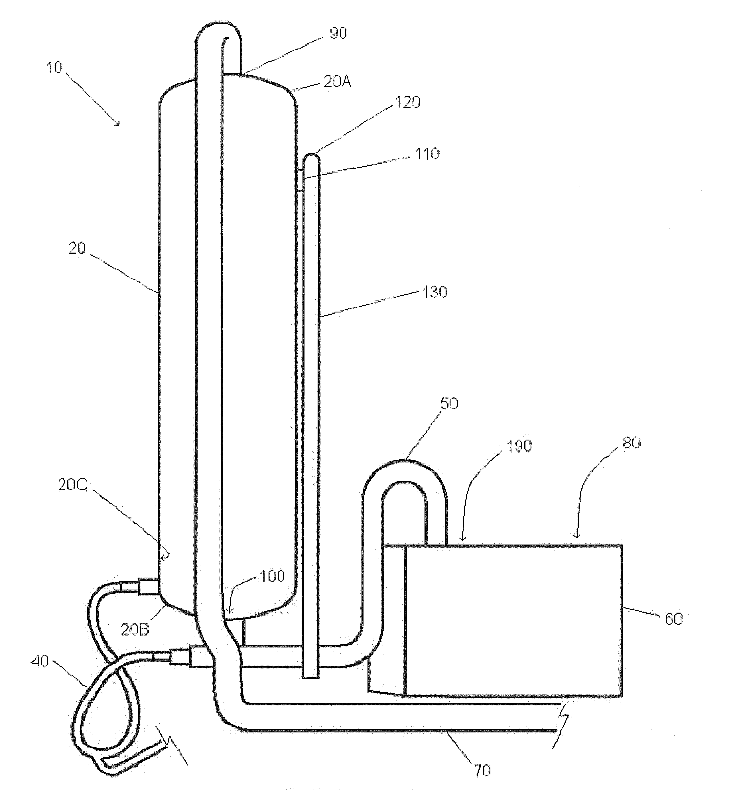
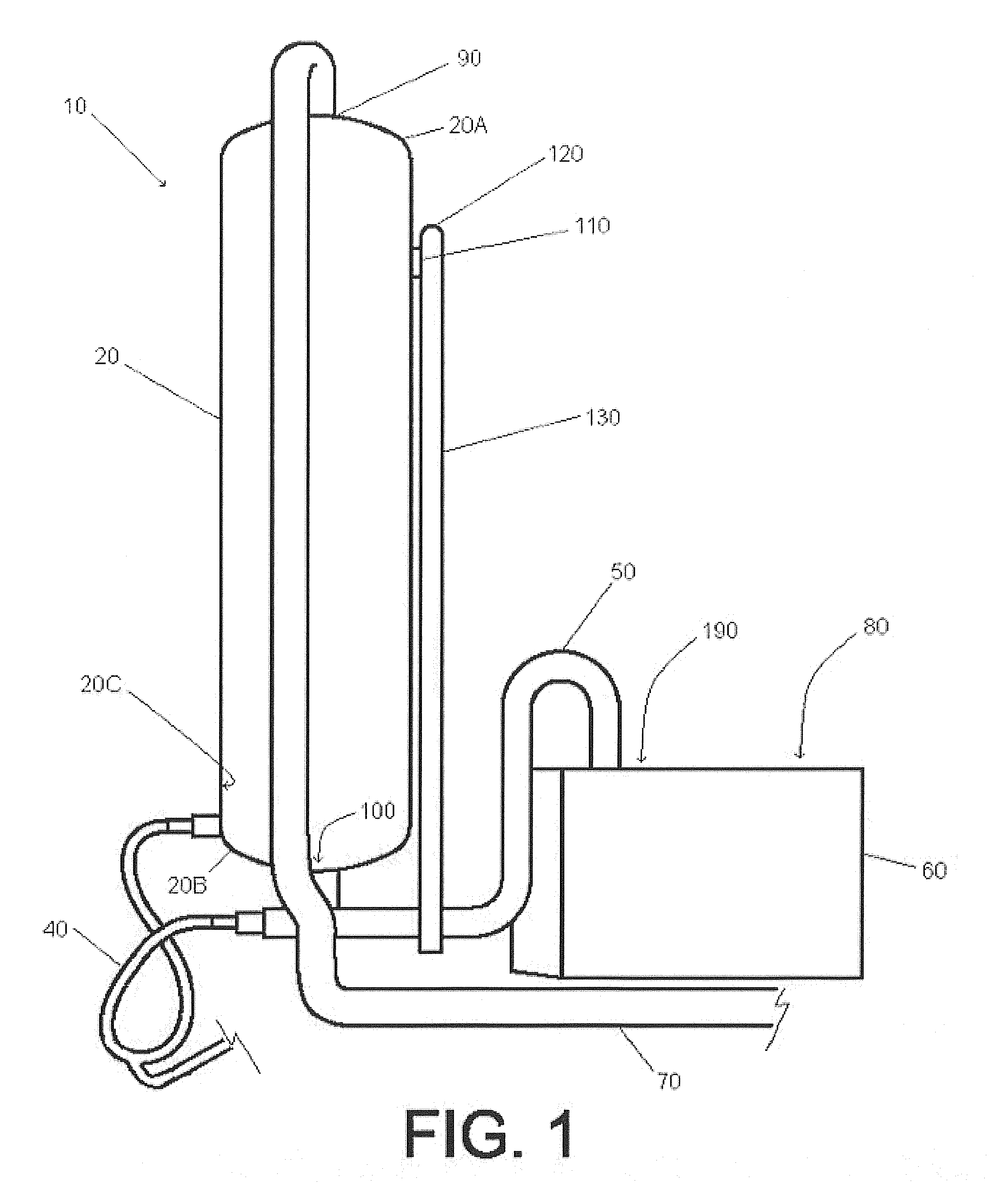
[0018]Referring to the figures, FIG. 1 illustrates the gas buster 20, which receives the initial pumping of the oil / water mixture. The oil / water mixture contains many contaminants to the oil in addition to water. Some of the main contaminants are solids such as sand and soil. The gas separator 20 can generally be described, without limitation, as a generally cylindrical steel, pressure vessel, approximately ten (10) feet high with an inside diameter of approximately thirty (30) inches. The oil / water mixture travels within the oil separation unit 10, thus the components of the oil separation unit 10 are considered to be in fluid communication with one-another.

[0019]The gas separator 20 is closed, with the exception of the inlet 90, outlet 100 and a gas vent port 110 which is connected to a vent 120. A vent line 130 discharges gaseous matter that has separated from the water / oil mixture to a flare pit. The gas separator 20 has an inlet 100 opening positioned at the gas separator top 2...


PUM

PropertyMeasurementUnit
diameteraaaaaaaaaa
diameteraaaaaaaaaa
gravityaaaaaaaaaa

Abstract

An oil separation method and apparatus for the separation of acceptable oil from contaminated oil containing solids and liquids withdrawn from an oil well. A single oil skimming unit is partitioned into compartments and provided with rotating skimming tubes. A water leg may be raised and lowered in order to maintain a constant fluid level in the first, or water, compartment. Two pump jets are incoporated into the neck of the gas separator in order to continually move the solid contaminants so that they are not as able to settle and block fluid flow in the gas separator.

Description

[0001]This application is based upon and claims priority from U.S. Provisional application Ser. No. 61 / 613,755, which is incorporated herein by reference.BACKGROUND OF THE INVENTION[0002]1. Field of the Invention[0003]The present invention relates to oil separation systems for oil field facilities. More particularly, the present invention is a method and apparatus for the continuous separation of oil from solid and liquid contaminants at the site of oil field drilling operations.[0004]2. Background Information[0005]Traditionally, the current method for separating oil (Petroleum, hydrocarbons, oil, and crude oil are collectively referred to as “oil”) from gaseous, solid, and liquid contaminants involved the use of a multiplicity of open-top separation tanks in which contaminated oil withdrawn from the well is allowed to settle out or separate by gravity. As contaminated oil was withdrawn and directed to the first tank, the heavier solids fell to the bottom of the first tank and light...

Claims


Application Information

Patent Timeline
Patent Type & Authority Applications(United States)
IPC IPC(8): B01D19/00
CPCB01D19/0057B01D17/0208B01D19/0042B01D21/0048B01D21/0021B01D21/0087B01D21/2472B01D21/2494B01D2221/04
Inventor WARNCKE, GLENWOOD
Owner HORIZONTAL RENTALS
Why Eureka
Try Eureka