Top cover assembly for a monitoring camera

Active Publication Date: 2013-10-31
AXIS
View PDF13 Cites 47 Cited by
  • Summary
  • Abstract
  • Description
  • Claims
  • Application Information

AI Technical Summary

Benefits of technology

[0009]An object of the present invention is to simplify

Problems solved by technology

This may be a cumbersome process, as the lining is placed on the inside of the dome and its position must be manipulated by the operator

Method used


Image

  • Top cover assembly for a monitoring camera
  • Top cover assembly for a monitoring camera
  • Top cover assembly for a monitoring camera

Examples


Example

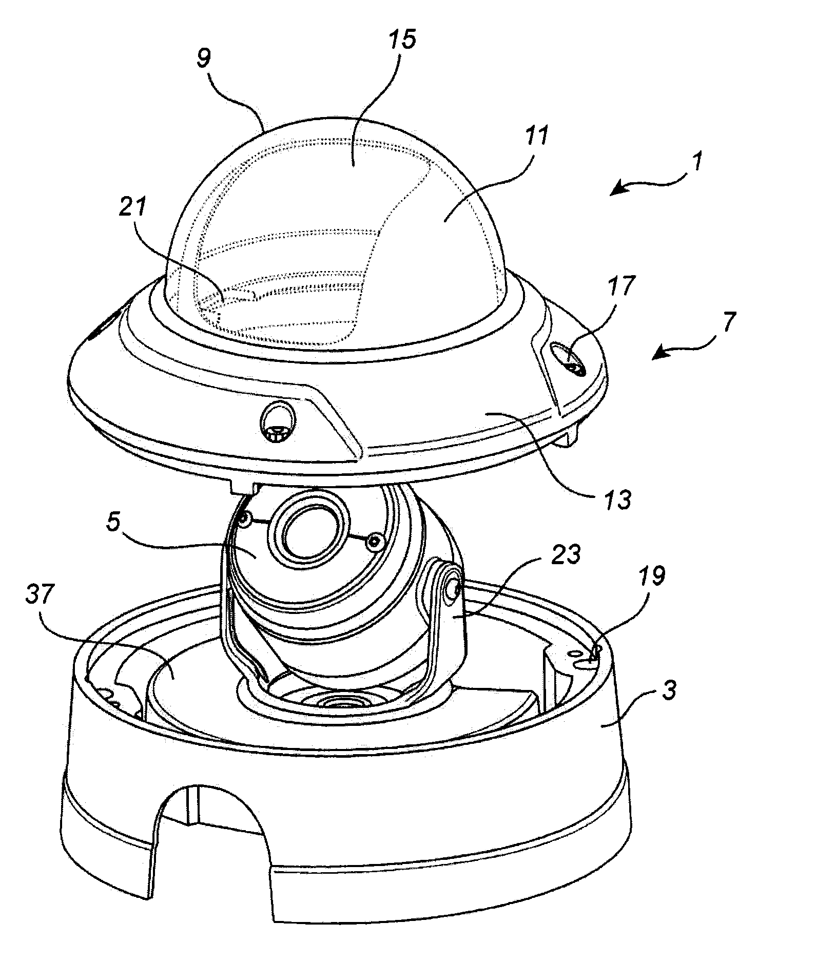
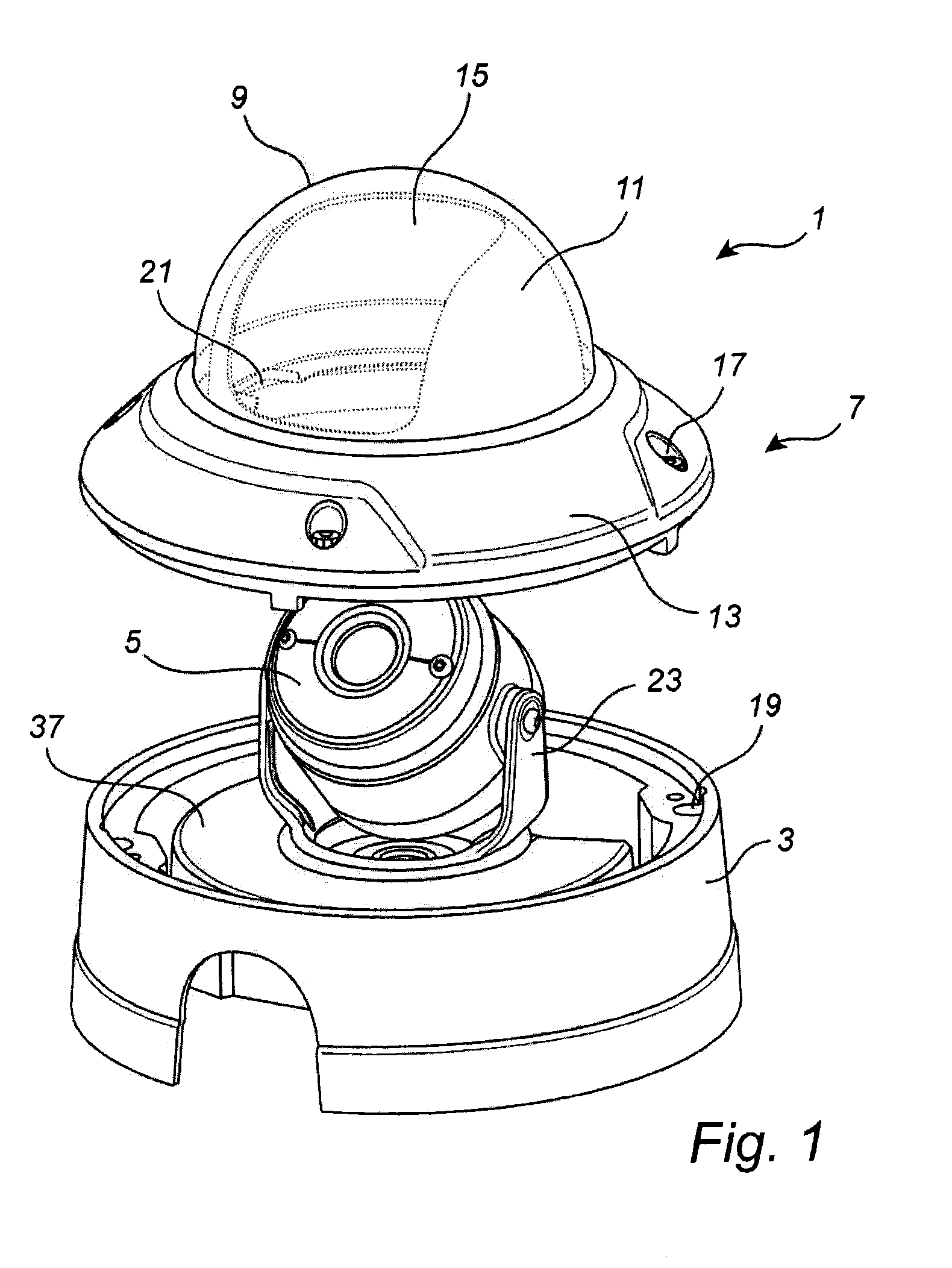
[0040]FIG. 1 shows a top cover assembly 1 and a mounting base 3 with a monitoring camera 5. The top cover assembly 1, the mounting base 3, and the monitoring camera 5 together form a monitoring camera assembly 7. The top cover assembly 1 comprises a dome window 9, a lining 11 and a mounting portion 13. The lining 11 is rotatable in relation to the mounting portion 13 and has an opening 15 adapted to the size and shape of a field of view of the camera 5. The lining 11 is provided to protect the camera 5 from reflexes from the dome window 9.

[0041]The lining 11 may be made of an opaque material, such as a non-transparent plastic material. The dome window 9 is normally made of a transparent material, such as a transparent plastic material. To protect the camera 5 against outside forces, the dome window 9 may be made of a material strong enough to be able to withstand a certain amount of blows and hits.

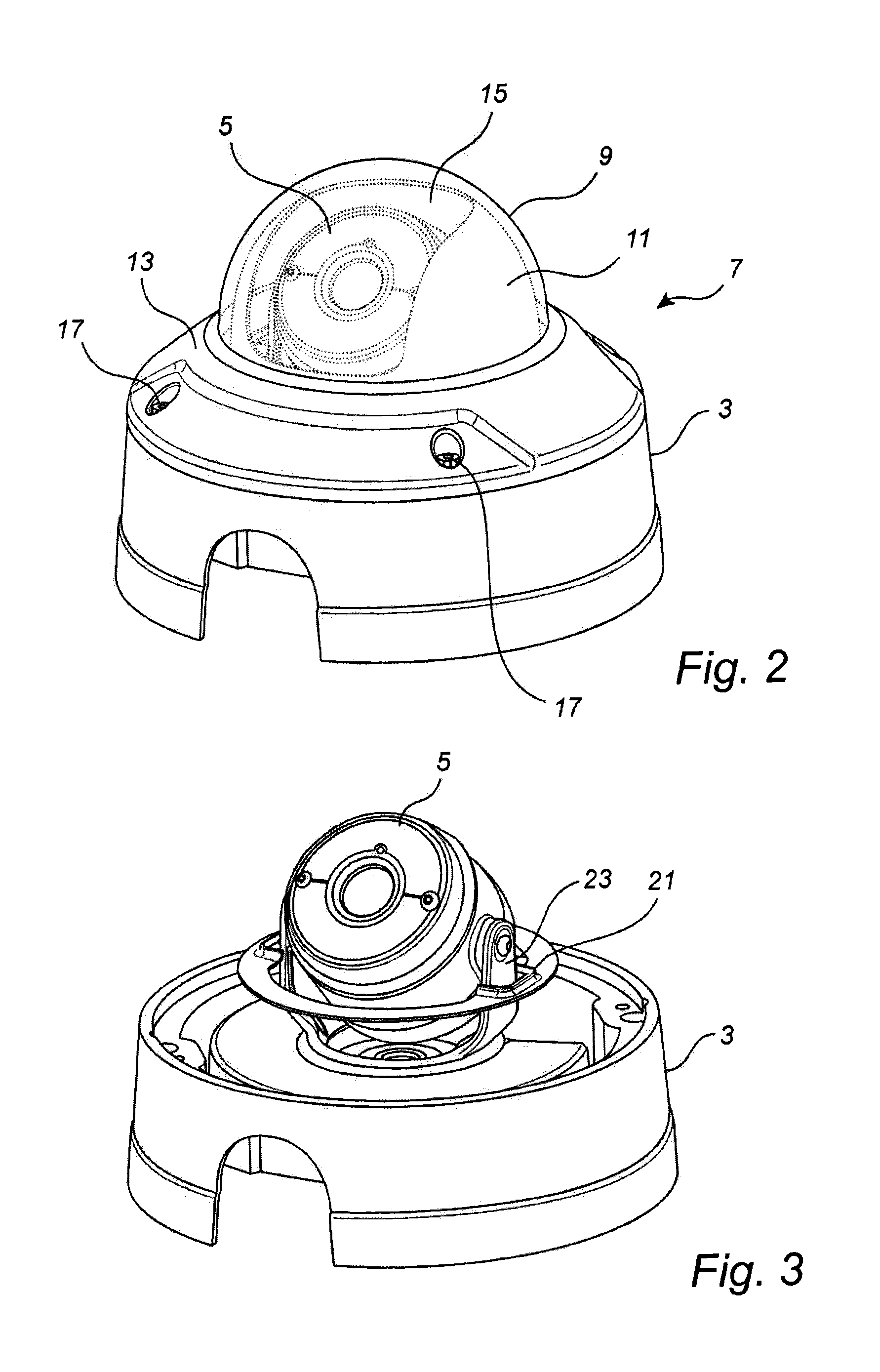
[0042]FIG. 2 shows the monitoring camera assembly in mounted position where the mounti...


PUM


Abstract

A top cover assembly (1) for a monitoring camera assembly comprises a mounting portion (13) arranged for attachment to a mounting base (3) for a monitoring camera (5), a dome window (9) arranged on the mounting portion (13) and a lining (11) arranged at an inside of the dome window (9), the lining (11) having a camera view opening (15) adapted to a field of view of the monitoring camera (5) and being rotatable in relation to the mounting portion (13).
The lining (11) has a guiding portion (21) arranged for engagement with a camera mounting bracket (23) on the mounting base (3) to position the lining (11) in relation to the monitoring camera (5) such that the camera view opening (15) covers the field of view of the monitoring camera (5), when mounting the top cover assembly (1) on the mounting base (3), thereby allowing the mounting portion (13) to be rotated in relation to the lining (11) into a position for attaching the mounting portion (13) to the mounting base (3).

Description

CROSS-REFERENCE TO RELATED APPLICATION[0001]The present application claims the benefit of the earlier filing date of U.S. Provisional Patent Application Ser. No. 61 / 638,305, filed on Apr. 25, 2012, and EP Application No. 12165481.8, filed on Apr. 25, 2012, the entire contents of each of which being incorporated herein by reference.TECHNICAL FIELD[0002]The present invention relates to a top cover assembly for a monitoring camera.TECHNICAL BACKGROUND[0003]Monitoring cameras are commonly used for monitoring areas both indoors and outdoors, such as bank offices, department stores or public places. The camera is in some cases arranged for dynamic panning and tilting in order to enable image acquisition from different positions in the specific area, and in some cases the camera is panned and tilted to a desired fixed position by an operator when installing the camera. The latter alternative is often denoted a fixed camera installation.[0004]The camera is usually covered by a dome window w...

Claims


Application Information

Patent Timeline
IPC IPC(8): G03B17/56
CPCH04N5/2252G03B17/561G03B37/02H04N23/51
Inventor ANDERSSON, JOHAN
Owner AXIS
Why Eureka
Try Eureka