
Kitchen cabinet installation device

Active Publication Date: 2017-02-02
YOUNG
View PDF2 Cites 32 Cited by
  • Summary
  • Abstract
  • Description
  • Claims
  • Application Information

AI Technical Summary

Benefits of technology

The patent describes a box that consists of a base and a top cap. The top cap acts as a support plate for lifting and holding items like kitchen cabinets. Both the bottom base and the top cap have smooth surfaces to protect counter tops and cabinets. This invention is ideal for special needs cabinets and handicapped kitchens as it is low-profile and can fit in narrow spaces.

Problems solved by technology

In addition, the cabinets can be very heavy, which again may require two people to lift and align them to a desired vertical position.
However, the prior art devices have several drawbacks.
Many of them are very bulky and difficult to use.
Therefore, installer is not able to easily carry them around and they are not very portable.
Some of the prior art devices are portable but they are not proper for precise lifting and alignment.
Only, a few millimeter misalignments may destroy the look of a valuable cabinet.
The prior art devices are also prone to slippage and tilting of the cabinet during the installation.
Another drawback of the prior art devices is that they do not become compact enough to fit in the limited spaces between the base cabinets and upper wall cabinets or corners.

Method used


Image

  • Kitchen cabinet installation device
  • Kitchen cabinet installation device
  • Kitchen cabinet installation device

Examples


Embodiment Construction

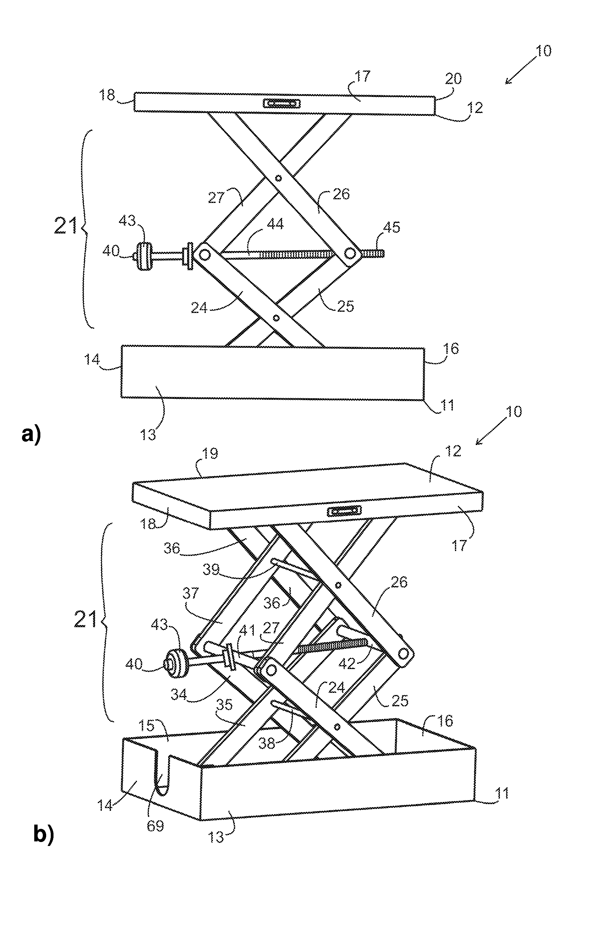
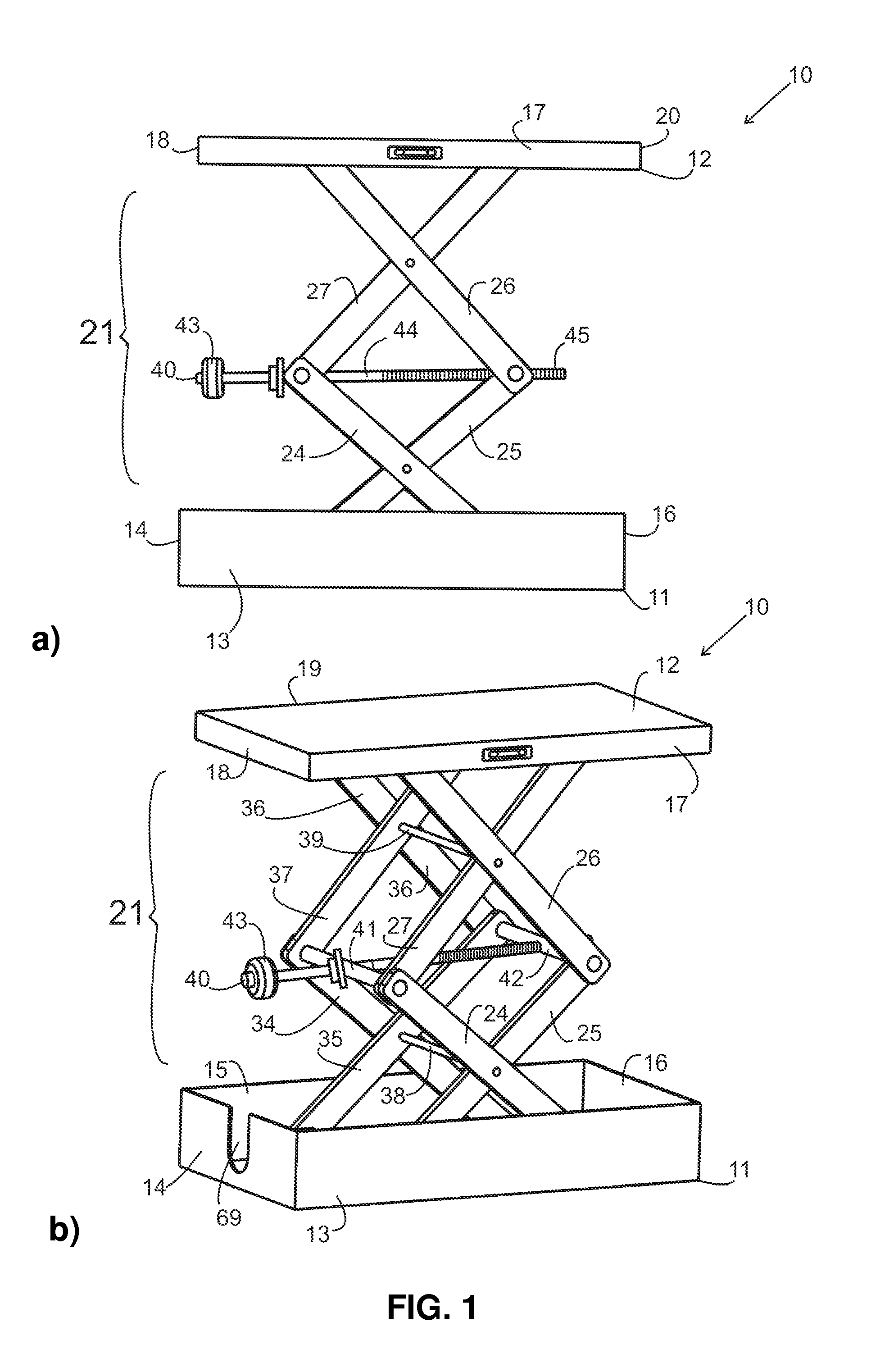
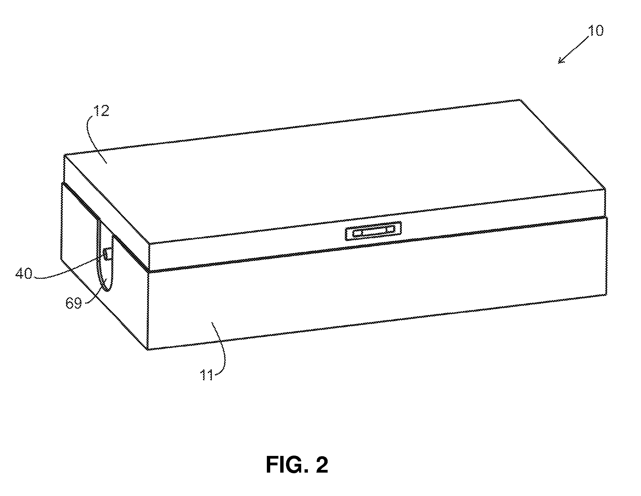
[0036]A cabinet installation device 10 according to the present invention is shown in FIGS. 1(a) and 1(b), comprising of a rectangular shaped box having a base part 11 and top cap 12. The base part have a dimensions of 17 inches in length, 9¾ inches in width and a 3¾ in depth. The base part 11 including opposing sidewalls 13, 15 and 14,16 fixedly attached. The top cap further having a dimensions of 17 inches in length, 9¾ inches in width and 2 inches in depth. The cap 12 including opposing sidewalls shown by the numeral 17, 19 and 18, 20. A scissor jack 21 mounted into the box so that the bottom end of the scissor jack is secured to the base part 11 of the box and the top end of the jack is attached underneath the top cap 12 of the box. The box is constructed of H.D.P.E (polyethylene with high density) and the jack is made if aluminum to enhance a lightweight to be easily transported.

[0037]FIG. 2 shows the installation device 10 in collapsed position which is a rectangular box havin...


PUM


Abstract

A kitchen cabinet installation device to install upper wall cabinets and suspended cabinets is provided. The kitchen cabinet installation device of the present invention is a lightweight box for easy transportation and to provide an easy and quick installation procedure with precision and make the installation procedure a one man job. The kitchen cabinet installation device includes a box having a base and a cap, and a double scissor jack installed into the box. The box features rails with rollers to provide a smooth movement of the jack. The jack includes a lead screw. By cabinet installation the object is placed on the cap and is lifted by turning the knob in lead screw and held during the installation in a secure position.

Description

FIELD OF THE INVENTION[0001]The present invention relates generally to a cabinet installation device and more particularly to a lifting and supporting device for mounting upper wall cabinets at a designated height.BACKGROUND OF THE INVENTION[0002]Cabinet installation procedure usually requires more than one person. In order to secure the cabinets in the kitchen, in view of the size of the cabinets, a standard of two installers are involved to complete the installation. One installer holds the cabinet in the designated place, while the other installer secures the cabinet to the wall. In addition, the cabinets can be very heavy, which again may require two people to lift and align them to a desired vertical position.[0003]The prior art discloses various devices to make cabinet installation easier, less time consuming and allow for a more accurate alignment. For example, various jack type devices have been suggested to lift the cabinet to a desired installation level. However, the prio...

Claims


Application Information

Patent Timeline
IPC IPC(8): E04F21/00F16M11/38B66F3/22E04G21/16E04G21/18A47B77/00F16M11/18
CPCE04F21/00A47B77/00F16M11/38B66F3/22E04G21/163E04G21/1841F16M11/18B66F7/0608B66F7/0666
Inventor YOUNG, RONALD
Owner YOUNG
Learn More