Pneumatic vertical rotating suction machine and utility unit thereof

A technology of vertical rotation and suction cup machine, which is applied in the direction of load hanging components, transportation and packaging, etc. It can solve the problems of high risk factor, long vacuum time consumption, inconvenient shaking control, etc., and achieve high efficiency, damage protection, and increased safety. Effect

Inactive Publication Date: 2012-01-11
深圳市创思泰科技有限公司
View PDF4 Cites 3 Cited by
  • Summary
  • Abstract
  • Description
  • Claims
  • Application Information

AI Technical Summary

Problems solved by technology

[0002]The existing handling equipment for handling flat plates uses the lifting of electric chain hoists and the simple expansion and contraction of cylinders, and the vacuum pump generates vacuum to absorb and transport the plates; or use cranes to hang fixtures Handling board...

Method used


Image

  • Pneumatic vertical rotating suction machine and utility unit thereof
  • Pneumatic vertical rotating suction machine and utility unit thereof
  • Pneumatic vertical rotating suction machine and utility unit thereof

Examples


Embodiment Construction

[0043] The present invention will be further described below in conjunction with the accompanying drawings and specific embodiments.

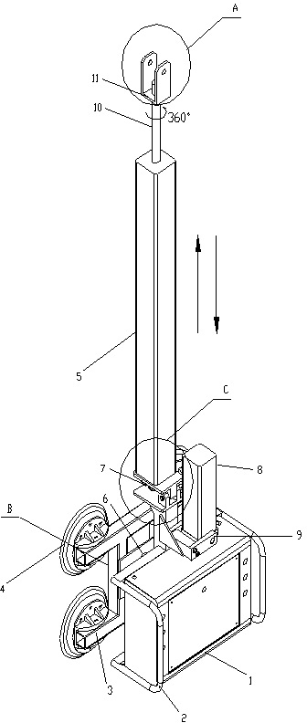
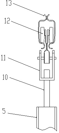
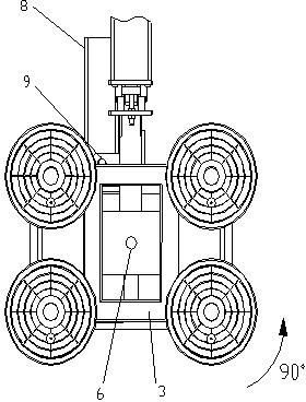
[0044] A pneumatic vertical rotary suction cup machine, which is composed of two sets of parts, one is the suspension part: column type or wall type cantilever crane (the fixed cantilever method is selected according to the characteristics of different sites of customers), the sliding trolley is suspended and slid in the Ω track; the other is Pneumatic vacuum suction cup machine, using the telescopic function of two cylinders and the mechanical cooperation of the mechanical shaft to realize the lifting and vertical rotation of the machine, using the high-efficiency and stable characteristics of the vacuum generator, the vacuum pressure is controlled by the ventilation valve, one-way valve, and pneumatic control components. During the conversion of flow control, the machine generates vacuum pressure to absorb the sheet in an instant. The suction...


PUM


Abstract

The invention provides a pneumatic vertical rotating suction machine and a utility unit thereof. The suction machine comprises two parts, one is a suspension portion comprising a column or wall cantilever crane and a sliding carriage which slides along with the KBK type omega track with hanging; and the other is a pneumatic vacuum suction machine which is characterized in that by using the mechanical cooperation of expansion function of two cylinders and a mechanical shaft, lifting and vertical rotating motion of the machine are realized, and by using the characteristics of high efficiency and stability of a vacuum generator, in the flow control conversion of a scavenging valve, a non return valve and a pneumatic controlling element, vacuum pressure lets the machine instantly generate a vacuum pressure adsorption board. According to the invention, the suction machine hangs on the sliding carriage on the hanger rail and rotates coordinating with the cantilever crane, so that, the carrying production of the adsorption board can be lifted, translated, and rotated in the orbital radius of 270 DEG by a user.

Description

technical field [0001] The invention relates to lifting and conveying equipment, in particular to a suction cup machine. Background technique [0002] The existing handling equipment for handling flat plates uses the lifting of the chain electric hoist and the simple cylinder expansion, and the vacuum pump generates a vacuum to absorb and transport the plates; or use the crane to hang the jig to transport the plates; the chain lifts the plates, the shaking is obviously inconvenient to control, and the risk factor is relatively low. Big. It takes a long time for the vacuum pump to generate a vacuum; the working efficiency of the crane is extremely low, and the risk factor of the hanging fixture is extremely high. [0003] In the current production process, there are many situations where large plates need to be moved, such as glass, stone, steel plates, etc., and it is urgent to provide a simple, safe, and rotating handling equipment. Specifically, one person can operate th...

Claims


Application Information

Patent Timeline
IPC IPC(8): B66C1/02B66C13/04
Inventor 何东亮彭志斌
Owner 深圳市创思泰科技有限公司
Why Eureka
Try Eureka