Solar thermal panel and method of manufacture

Inactive Publication Date: 2010-03-18
AVENCROFT
View PDF15 Cites 11 Cited by
  • Summary
  • Abstract
  • Description
  • Claims
  • Application Information

AI Technical Summary

Benefits of technology

[0024]In contrast to the prior art, the solar panel will be mounted onto the roof apex, rather than being mounted onto the sloping side of the roof (usually south-facing). This factor will greatly simplify the installation process. The hinging of the ridge panels will allow them to be fitted to roofs of any apex angle easily and with an equal weight distribution, thus r

Problems solved by technology

Flat panel systems are generally less costly per unit area but are typically 15-30% less efficient compared to evacuated tube systems.
Current flat panel solar thermal systems lose heat during thermal conduction along the heat transfer plates, this is the main cause of low efficiency.
Flat plate systems have almost reached the limit of their efficiency, and only small steps are expected beyond current efficiency levels.
However the current systems are relatively expensive, with a payback period of ˜12-15 years.
This cost is due to the high costs of both the manufacturing and installation.
The high manufacturing costs are due to the labour intensive nature of the manufacturing process that uses traditional metal working technolog

Method used


Image

  • Solar thermal panel and method of manufacture
  • Solar thermal panel and method of manufacture
  • Solar thermal panel and method of manufacture

Examples


Example

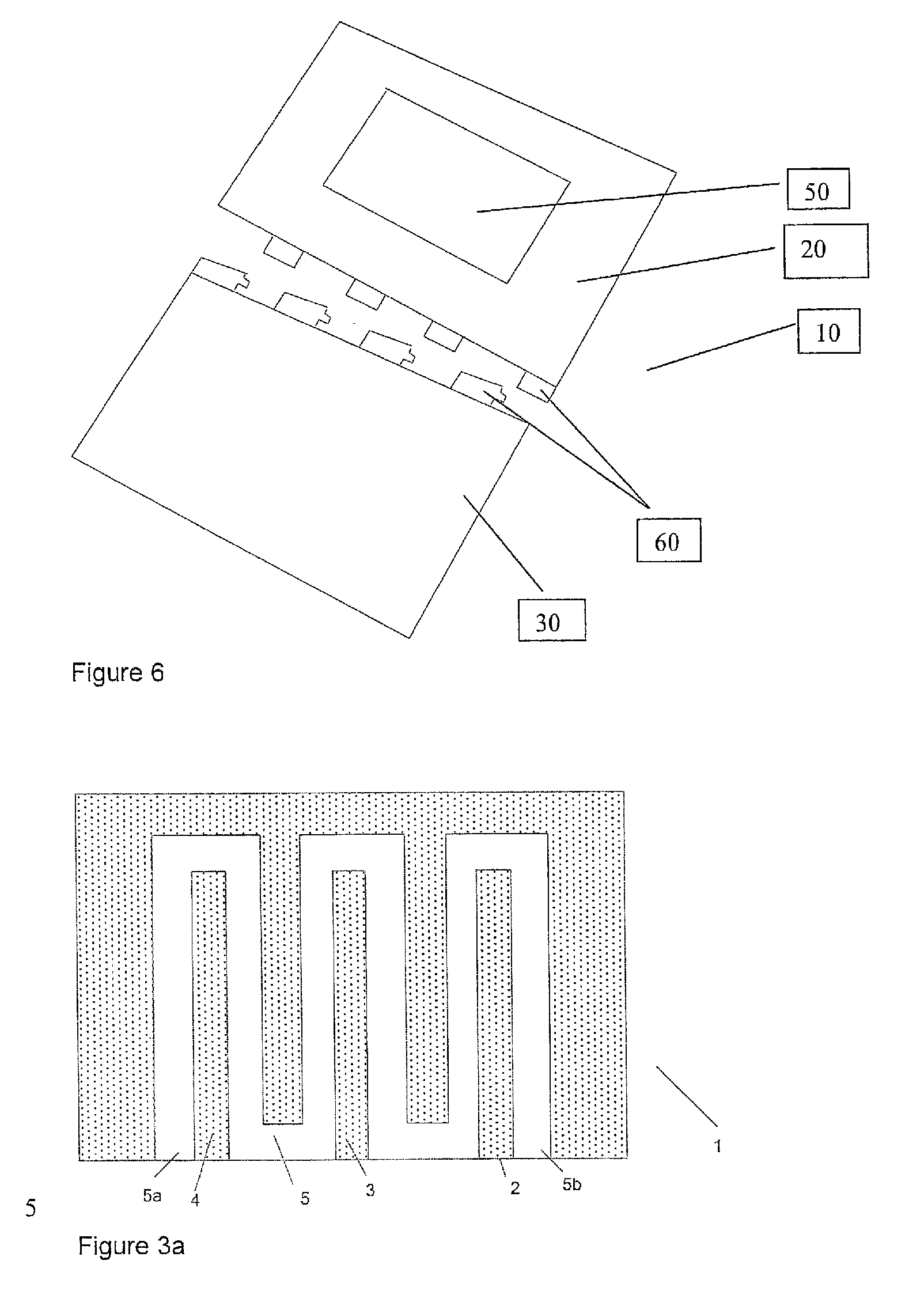
[0037]FIG. 3a is a schematic diagram of a solar thermal panel according to an embodiment of the present invention. The solar thermal panel 1 comprises a body 2 formed from rubber particles 3 bound by a binding agent such as a thermoplastic material 4 (referred to as the “matrix”). The body 2 includes one or more fluid channels 5. The distribution of particles in the matrix is illustrated as being uniform and this is desirable where uniform energy absorption and structural integrity is required; However, non uniform distribution may be beneficial in some cases where the differing physical properties of the matrix and rubber particles could be harnessed advantageously to provide additional features relating to functionality or strength.

[0038]The or each fluid channel includes a fluid inlet 5a and a fluid outlet 5b for connection to a fluid circulation circuit 5c.

[0039]Preferably, the rubber particles 3 comprise a rubber crumb material. Most preferably, the source of the rubber crumb ...


PUM

PropertyMeasurementUnit
Diameteraaaaaaaaaa
Diameteraaaaaaaaaa
Pressureaaaaaaaaaa

Abstract

A solar thermal panel is disclosed. The solar thermal panel includes a body, the body comprising a plurality of rubber particles bound by a binding agent and defining one or more channels within the body, the or each channel including a fluid inlet and a fluid outlet connectable to a fluid circulation circuit.

Description

FIELD OF THE INVENTION[0001]The present invention relates to solar thermal panels that are particularly applicable for use in low cost, roof mounted systems for domestic water heating and / or generating electricity.BACKGROUND TO THE INVENTION[0002]Solar Thermal panels absorb solar radiation directly and use this to heat either air or water. Two types of solar thermal systems are commonly used:Evacuated tubes and flat panels.[0003]Flat panel systems are generally less costly per unit area but are typically 15-30% less efficient compared to evacuated tube systems. The typical cross section for a flat panel system is shown in FIG. 1. The solar radiation is absorbed by the selective coating and the thermal energy then transferred along the heat transfer plate and used to heat the water that circulates in the water pipes. The panels are typically mounted in an aluminium housing with thermal insulation provided by the glazing on the top surface and foam insulation on the under surface.[000...

Claims


Application Information

Patent Timeline
IPC IPC(8): F24J2/48B23P15/26
CPCF24J2/045F24J2/5228F24J2002/5486Y02B10/12Y10T29/49355Y02E10/44Y02E10/47H02S20/23Y02B10/20F24S10/45F24S20/67F24S25/40F24S2030/16Y02B10/10Y02E10/50
Inventor READER, JOHN EDWARD HUBBARDBUCKLES, DAVID JOHNBROOKS, NICOLASJONES, ANDREW
Owner AVENCROFT
Why Eureka
Try Eureka