
Image forming apparatus

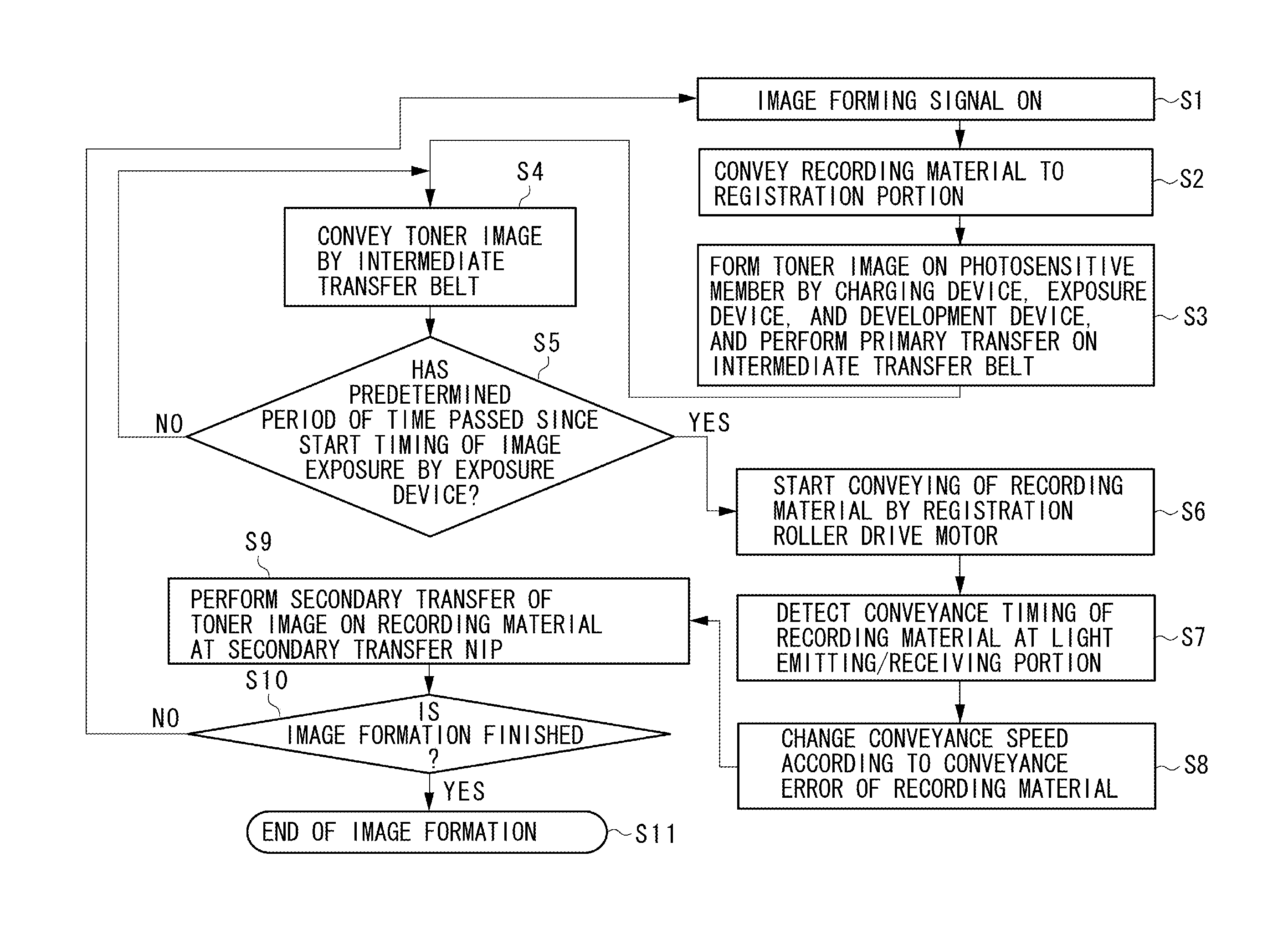
a technology of image forming apparatus and registration portion, which is applied in the direction of electrographic process apparatus, instruments, optics, etc., can solve the problems of long operating time for adjustments, difficult to ensure the relative positions of the first and second detection portions, and not always meeting the demand for the higher accuracy of leading edge registration

Active Publication Date: 2013-10-31
CANON KK
View PDF3 Cites 5 Cited by
  • Summary
  • Abstract
  • Description
  • Claims
  • Application Information

AI Technical Summary

Benefits of technology

The invention provides an image forming apparatus that does not require adjusting the position of two detection parts when replacing a unit.

Problems solved by technology

The leading-edge registration by the registration portion does not always meet the demand for the higher accuracy of leading edge registration.
However, the structure including a first detection portion disposed at a first guide, a second detection portion disposed at a second guide, and a first guide which is supported by an image forming unit, and a second guide which is disposed at a drawable unit has the following problems.
Since there are many parts in the conventional positioning structure, it is difficult to assure relative positions of the first and the second detecting portions.
Thus, the operating time for adjustments becomes long and the operating cost therefor becomes high.

Method used


Image

  • Image forming apparatus
  • Image forming apparatus
  • Image forming apparatus

Examples


Embodiment Construction

[0035]Various exemplary embodiments, features, and embodiments of the invention will be described in detail below with reference to the drawings.

[0036](Structure of Entire Image Forming Apparatus)

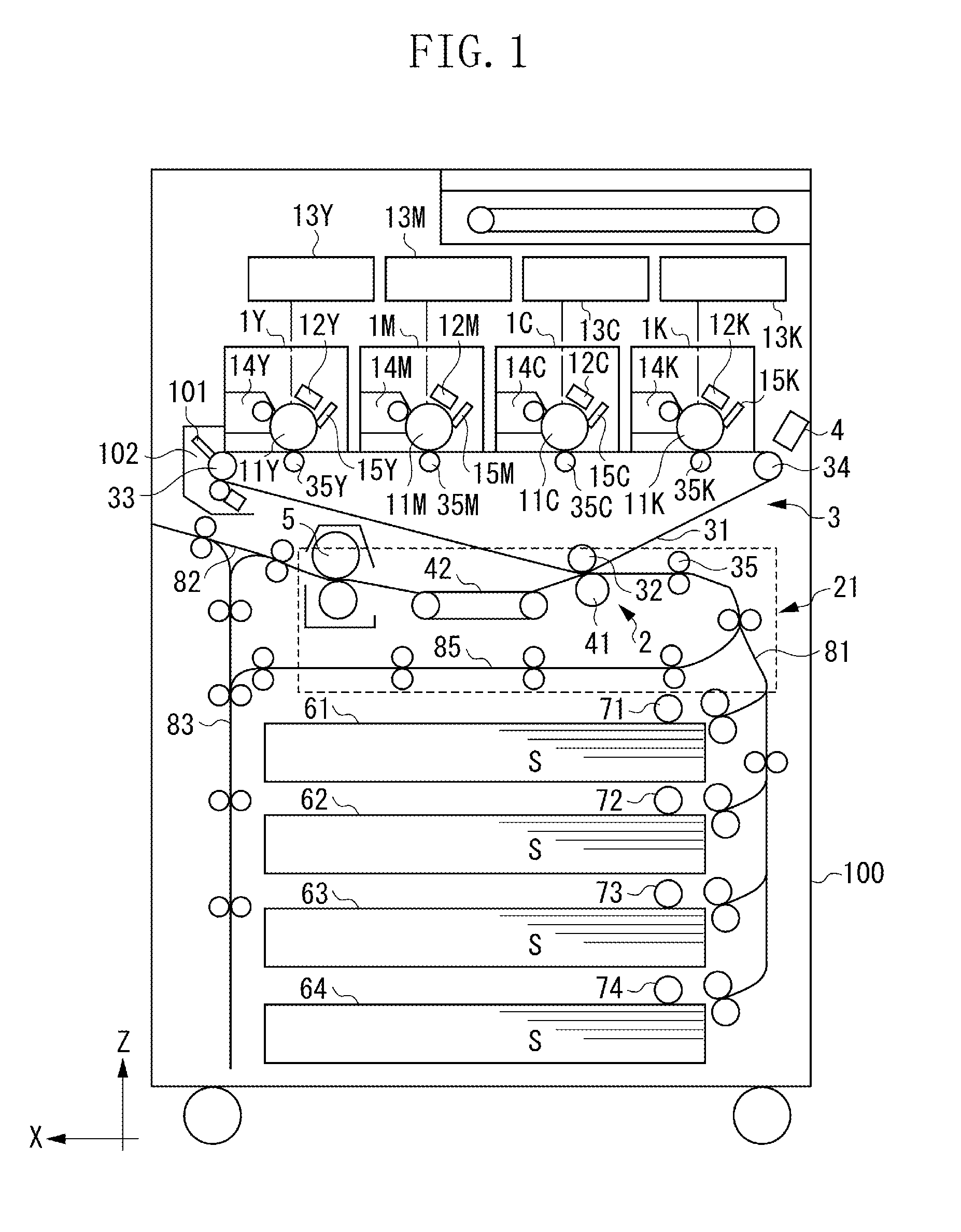
[0037]A first exemplary embodiment of the present invention will be described below. FIG. 1 is a schematic cross-sectional view illustrating a color digital printer as a concrete example of an image forming apparatus including a secondary transfer portion (transfer portion) according to the exemplary embodiment of the present invention.

[0038]The surfaces of four photosensitive drums 11Y, 11M, 11C, and 11K are uniformly charged by chargers 12Y, 12M, 12C, and 12K, respectively.

[0039]Image signals of yellow (Y), magenta (M), cyan (C), and black (K) are input to laser scanners 13Y, 13M, 13C, and 13K, respectively. According to these image signals, the drum surfaces are irradiated with a laser beam and a latent image is formed.

[0040]The latent images formed on the photosensitive drums are develo...


PUM


Abstract

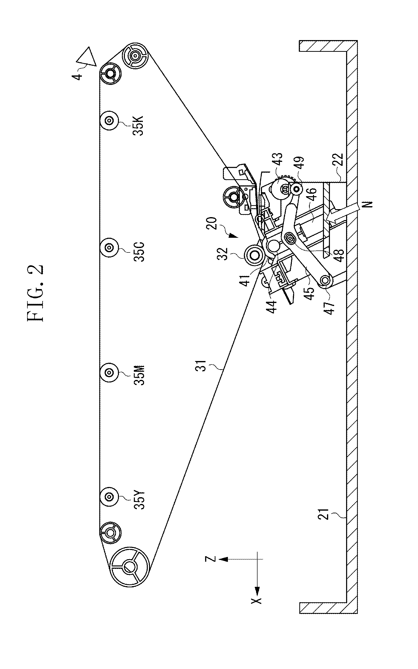
An image forming apparatus includes a first detection portion at a first guide provided in an image forming unit and a second detection portion at a second guide provided in a unit drawable to the exterior of the image forming apparatus. Since there are many parts in this apparatus, an error in the relative positions of the first and the second detection portions is large. The image forming apparatus includes a lock member configured to lock the unit to an image forming apparatus main body, and a pressure member configured to, when the unit is locked to the image forming apparatus main body, press the first guide and the second guide to each other. As a result, adjustment of the relative positions of the first and the second detection portions is not required at the time of replacement of the unit or the detection portions.

Description

BACKGROUND OF THE INVENTION[0001]1. Field of the Invention[0002]The present invention relates to an image forming apparatus, such as a copying machine, a facsimile, and a printer.[0003]2. Description of the Related Art[0004]In an image forming apparatus, such as a copying machine, a facsimile, and a printer, a recording material is conveyed to a registration portion to be aligned with an image (referred to as “leading-edge registration”, hereinafter).[0005]Recently, however, a demand for higher accuracy of leading-edge registration has been increasing in the market. The leading-edge registration by the registration portion does not always meet the demand for the higher accuracy of leading edge registration.[0006]Accordingly, a detection member for detecting timing at which a recording material passes may be provided at the upstream position of a transfer portion for the recording material in a recording material conveyance direction. Based on the output of the detection member, regi...

Claims


Application Information

Patent Timeline
Patent Type & Authority Applications(United States)
IPC IPC(8): G03G15/16
CPCG03G15/16G03G15/165G03G15/6564G03G21/168G03G2215/00721G03G2215/00945
Inventor TAOKA, KEITARO
Owner CANON KK
Learn More