In-mouth cavity tracing device

a tracing device and in-mouth cavity technology, applied in the field of tracing devices, can solve the problems of inability to determine the correct center position, the patient's load is heavier, and the natural movement of the lower jaw cannot, so as to prevent or eliminate shaking, prevent or eliminate the effect of shaking, and smooth detachment of these parts

Inactive Publication Date: 2007-10-04
CASTING IN
View PDF25 Cites 4 Cited by
  • Summary
  • Abstract
  • Description
  • Claims
  • Application Information

AI Technical Summary

Benefits of technology

[0047] Moreover, in the in-mouth cavity tracing device, ditches can be installed on the side wall of the lower jaw plate connection part assistance tool with two pins placed at the front and behind to prevent or eliminate shaking between the main body of the lower jaw plate, the guide tracing table, and the lower jaw plate connection part, and thus smooth detaching of these parts can be accomplished. The upper jaw plate can be adhered to the palate tightly, and the tongue can be prevented from pressing by locating the lower jaw plate upward, provided that the upper jaw plate and the lower jaw plate are to be U-shaped. Further, since the patient's tongue can be put in the hollow part of the lower jaw plate, it is possible to prevent the patient's tongue from being pressed by the lower jaw plate, and to also prevent the lower jaw plate from being lifted up by pressure of the tongue, which enables a precise measurement record.
[0048] Since a part or the whole of the connection pore installed in the above-mentioned upper jaw plate, the stud installation pore, the installation pore of the tracing pin, and the connection pore installed in the above-mentioned lower jaw plate can be formed with magnetic material or associated with a magnetic force, and screws are not necessary, the tracing operation in the above-mentioned in-mouth cavity can be easy and can be done in a short time.
[0049] Moreover, the materials such as pins can be made of a magnetic material for preventing loss or dropping of the pins in the mouth cavity. Whereas, in the related art, screws are clamped by hand, and integrated on the resin plate by using a lot of screws.
[0050] In concrete terms, detaching processes can be easily accomplished, and a complex operation such as tightening of screws in each exchange is not required, since the tracing pin, and the jaw fixing pin (tracing pin used together) can be fixed respectively to the tracing pin installation pore via magnetic force.
[0051] Since the guide prop stud can be fixed by magnetic force associated with the connection pore, it is easy to detach them for adjusting jaw intervals. The time required for clinical adjustment can be shortened because complex operation is not required.
[0052] In these connection release processes, the upper jaw plate connection part and the lower jaw plate connection part can be separated by loosening the plate interval fixing screw, and connection release can be done in a short time. In addition, the guide table, and the tracing table can be combined together as the guide tracing table, which is separately installed in the lower jaw plate in the conventional art, whereby the detaching process can be done at one time, and the detaching process is easy because installation with the lower jaw plate can be accomplished by fixing with the magnetic force associated with the connection pore. Therefore, each subcomponent in the mouth cavity can be quickly detached in the positioning process. Other processes are also simplified and made easier, including the record formation process of the guide plate in the clinic, the record formation process of the tracing plate, the Gothic arch tracing process, and the Check-bite collection process, for example. Moreover, in the tracing table placed forward of the guide tracing table, electrical connection of the tracing pin and metallic tracing plate is able to be detected. Therefore, when a small hole in the Check-bite collection process cannot be confirmed by interruption of the front teeth, it can be confirmed by an electric detector via lights, buzzer sounds, etc. (see FIG. 16).

Problems solved by technology

Moreover, in this Gothic arch tracer, a high diameter of bite is often required, which can be stressful and make a patient's load heavier.
Further, in the above condition, it is troublesome that natural movement of the lower jaw cannot be made, thus the correct center position cannot be determined.
As for the above-mentioned Gothic arch tracer, lots of troubles were found as listed above, since the position of APEX was difficult to confirm due to tracing in bold lines, and enough clearance space (space for no contact with upper and lower teeth) was typically necessary while recording.
However, there is a problem in that the guide prop stud 2 and / or other components can be easily loosened.
However, there is a fault in that it can be easily loosened in the process.
There is also possibilities of medical accidents occurring, for example, dropping screws, or conditioner tools in the mouth because of the small screw size, etc.
However, the operational formation process is insufficient and complex.
Moreover, in the connecting process to adjust the starting position where the horizontal position should be constant, since it is typically necessary to use the connecting shaft 14, the upper jaw plate supporter 16, the plate interval fixation screw 17, and the connecting screw 13 in the connecting process of the upper jaw plate A and the lower jaw plate B, by using the coupling tool C, the operational efficiency therefore is difficult and complex.
It is also difficult to make a plate that is universally appropriate to a patient's mouth cavity (jaw).
In addition, shaking is a problem at the time of detaching the guide tracing table and the lower jaw plate connection part from / to the main body of the lower jaw plate.

Method used


Image

  • In-mouth cavity tracing device
  • In-mouth cavity tracing device
  • In-mouth cavity tracing device

Examples


Embodiment Construction

[0071] Embodiments of the disclosed subject matter will now be described in detail with reference to FIGS. 1 to 7. The same reference numerals, etc. are used in the embodiments to refer to the same or similar structures and detailed explanation thereof is omitted.

[0072] Since the embodiments mentioned below are suitable, and concrete examples of the disclosed subject matter, certain features are technically fixed. However, the scope of the disclosed subject matter is not limited to the particular embodiments or the specific structures for each embodiment.

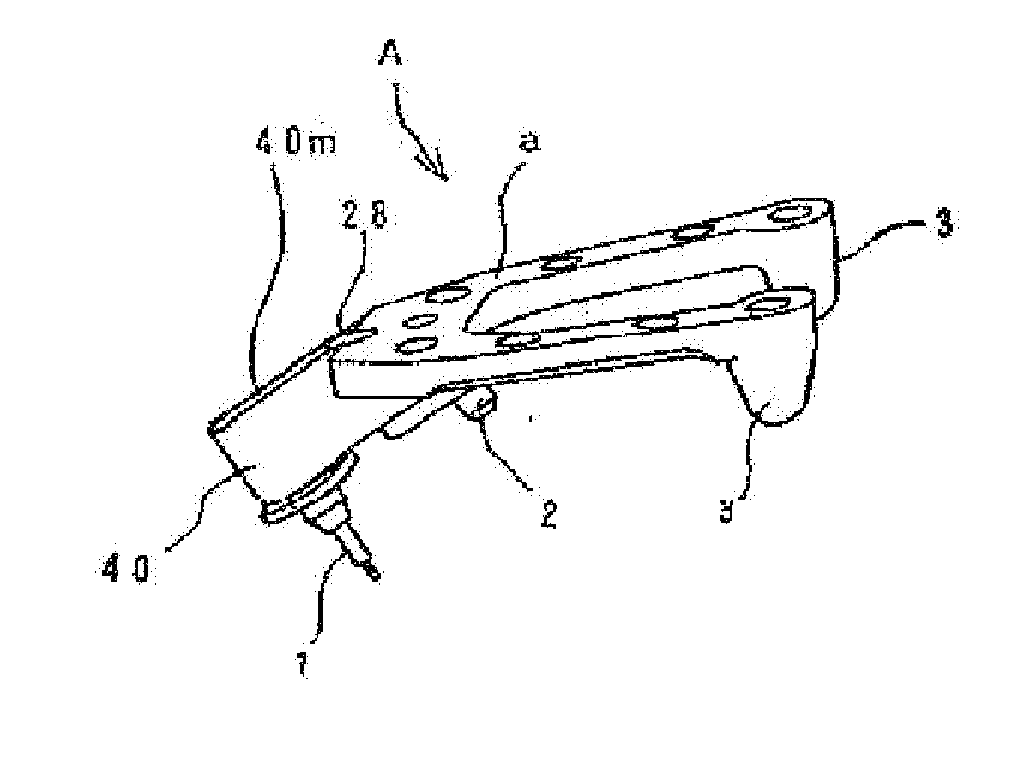
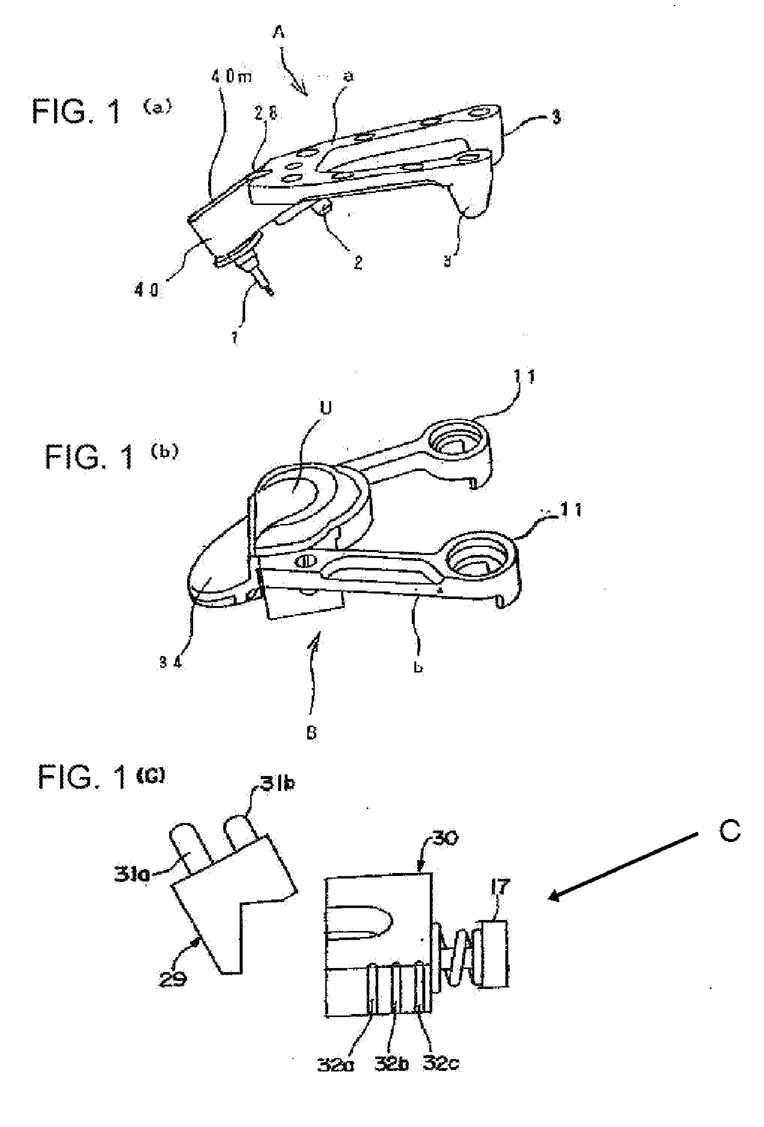
[0073] First of all, a summary outline of the disclosed subject matter is described as follows. The jaw-relator can include the upper jaw frame (plate), the lower jaw frame (plate), and the coupling tool that connects these jaw frames (plates) and locates them to the starting position in the mouth cavity. The upper jaw frame (plate) is installed in a bite floor of the upper jaw by, for example, an immediate polymerized resin, and ...


PUM


Abstract

A tracing device for use in the mouth cavity in which a center relation and a jaw movement are recorded in the odontology clinic can include an upper jaw plate, a lower jaw plate, and a coupling tool that connects the above jaw plates. The upper jaw plate can be provided with a guide prop stud, a stud installation pore, a tracing pin, a tracing pin installation pore as well as an auxiliary stud. The lower jaw plate can include a guide tracing table, a connection pore, as well as a movement line formation table. The coupling tool can include an upper jaw plate connection part, a lower jaw plate connection part as well as plate interval fixing screw. A part of, or the whole of, the connection pore, stud installation pore, tracing pin installation pore can be made of a magnetic material or associated with a magnet. The in-mouth cavity tracing device can include a lower jaw inducement guide plate made of plastic and having three dimensional slopes, and a guide tracing table having a tracing plate, and can be freely attachable/detachable to/from the main body of the lower jaw plate.

Description

BACKGROUND [0001] 1. Field [0002] The disclosed subject matter relates to a tracing device for use in a mouth when center relation and jaw movement are recorded in an odontology clinical. In the in-mouth cavity tracing device, a lower jaw inducement guide plate which can have the shape of three dimensional slopes including plastic, and a guide tracing table which has a tracing board are connected by pressure, and fitted to the main body of the lower jaw plate, and can all be freely detached in use. Also, an in-mouth cavity tracing device can include a lower jaw inducement guide plate shaped in three dimensional slopes having arbitrary angles. [0003] In recent odontology clinical studies, cases of using implantation, and ceramics, etc. as the newest odontology clinical materials, have been increasing. Also, in the in-mouth cavity tracing device, the desire for accurate measurement and recording of the position where a jaw movement, and the jaw itself are steady has been recognized. [...

Claims


Application Information

Patent Timeline
Patent Type & Authority Applications(United States)
IPC IPC(8): A61C19/04
CPCA61C19/05
Inventor KAWASAKI, TSUGUMICHI
Owner CASTING IN
Why Eureka
Try Eureka