Anti-thief security sensor assembly
a technology for security sensors and assembly parts, applied in the direction of optical radiation measurement, instruments, counting objects on conveyors, etc., can solve the problems of increased size, increased length of adjustment screws, and unnecessary increase of anti-thief security devices, so as to facilitate the simplification of the structure of the support member, easy operation, and easy adjustment
- Summary
- Abstract
- Description
- Claims
- Application Information
AI Technical Summary
Benefits of technology
Problems solved by technology
Method used
Image
Examples
first embodiment
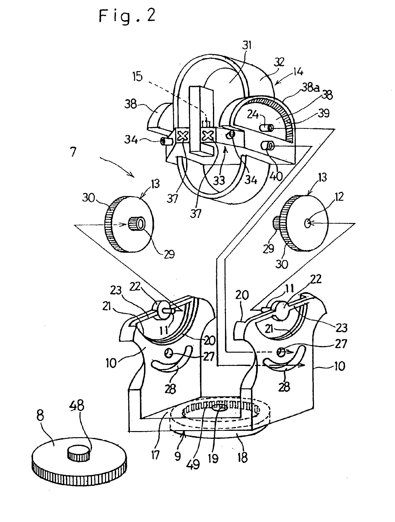
[0046]FIG. 4 schematically illustrates an important portion of the beam projecting or receiving device that forms an anti-thief security sensor assembly according to a second preferred embodiment of the present invention. Component parts shown in FIG. 4 similar to those shown in FIG. 3 are designated by like reference numerals used in FIG. 3 and, therefore, the detailed description thereof are not reiterated for the sake of brevity. In this anti-thief security sensor assembly shown in FIG. 4, in place of the driven gear 39 in the form of the internally threaded gear, a driven gear 41 in the form of an externally threaded gear is provided in the passive portion 38 of the optical unit 14 for engagement with the drive gear 29. Other structural features of the anti-thief security sensor assembly according to this embodiment are similar to those shown and described in connection with the
second embodiment
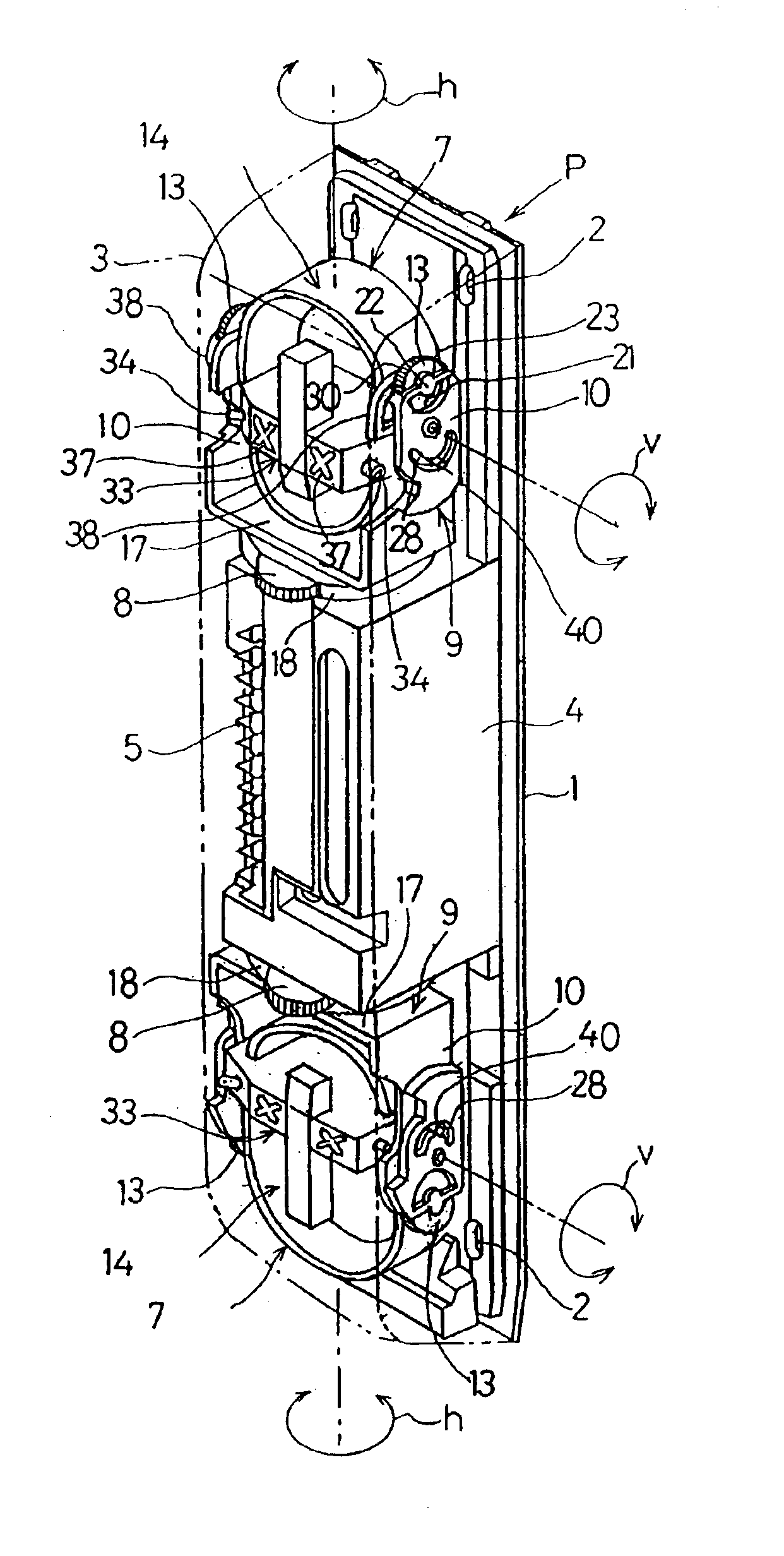
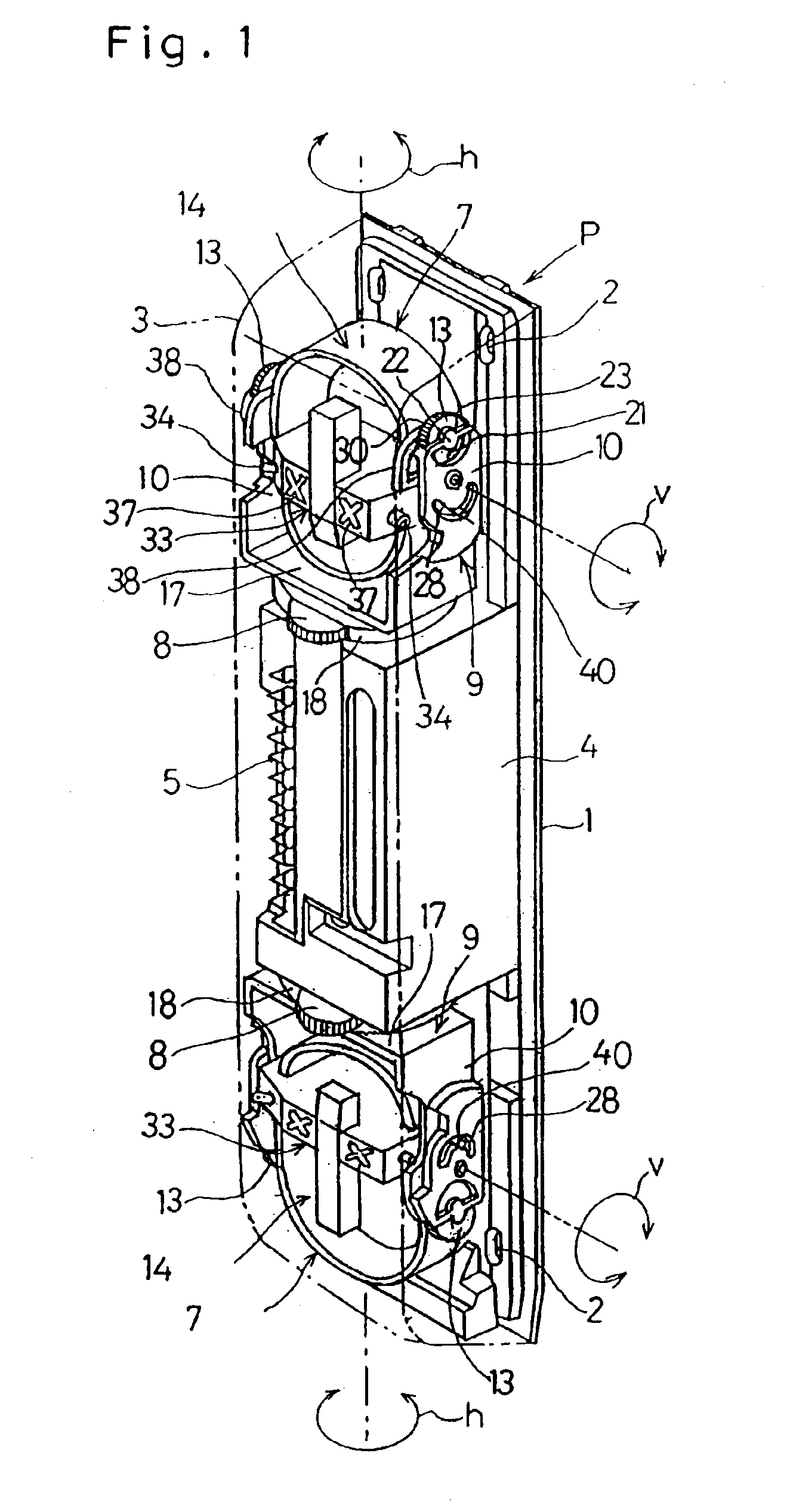
[0047] although the direction in which the vertical angle adjusting knob 13 is turned and the direction in which the optical unit 14 is turned are reverse to each other, this remains the same so far as the upper and lower beam projectors 7 positioned in a fashion inverted to each other are concerned. In other words, even in any one of the upper and lower beam projectors 7, the optical units 14 can turn in a direction reverse to the direction in which the vertical angle adjusting knobs 13 are turned. For this reason, there is no risk of an erroneous operation being performed when the attendant worker attempts an adjustment of the vertical angle of the optical unit 14 in each of the beam projectors 7.
[0048]It is to be noted that if one of the upper and lower beam projectors 7 employed in the beam projecting device P in the foregoing embodiment is replaced with a beam receiver, the resultant device will be a beam projecting and receiving device. Accordingly, an anti-thief security syst...
PUM
 Abstract
Description
Claims
Application Information
 - R&D
- Intellectual Property
- Life Sciences
- Materials
- Tech Scout
- Unparalleled Data Quality
- Higher Quality Content
- 60% Fewer Hallucinations
Browse by: Latest US Patents, China's latest patents, Technical Efficacy Thesaurus, Application Domain, Technology Topic, Popular Technical Reports.
© 2025 PatSnap. All rights reserved.Legal|Privacy policy|Modern Slavery Act Transparency Statement|Sitemap|About US| Contact US: help@patsnap.com


