
Re-calibration of instruments

a technology for recalibrating instruments and working parts, applied in instruments, specific gravity measurement, borehole/well accessories, etc., can solve problems such as inability to be true, high maintenance costs of pumps, and frequent re-builds of working parts

Inactive Publication Date: 2013-11-07
MEZURX
View PDF7 Cites 6 Cited by
  • Summary
  • Abstract
  • Description
  • Claims
  • Application Information

AI Technical Summary

Benefits of technology

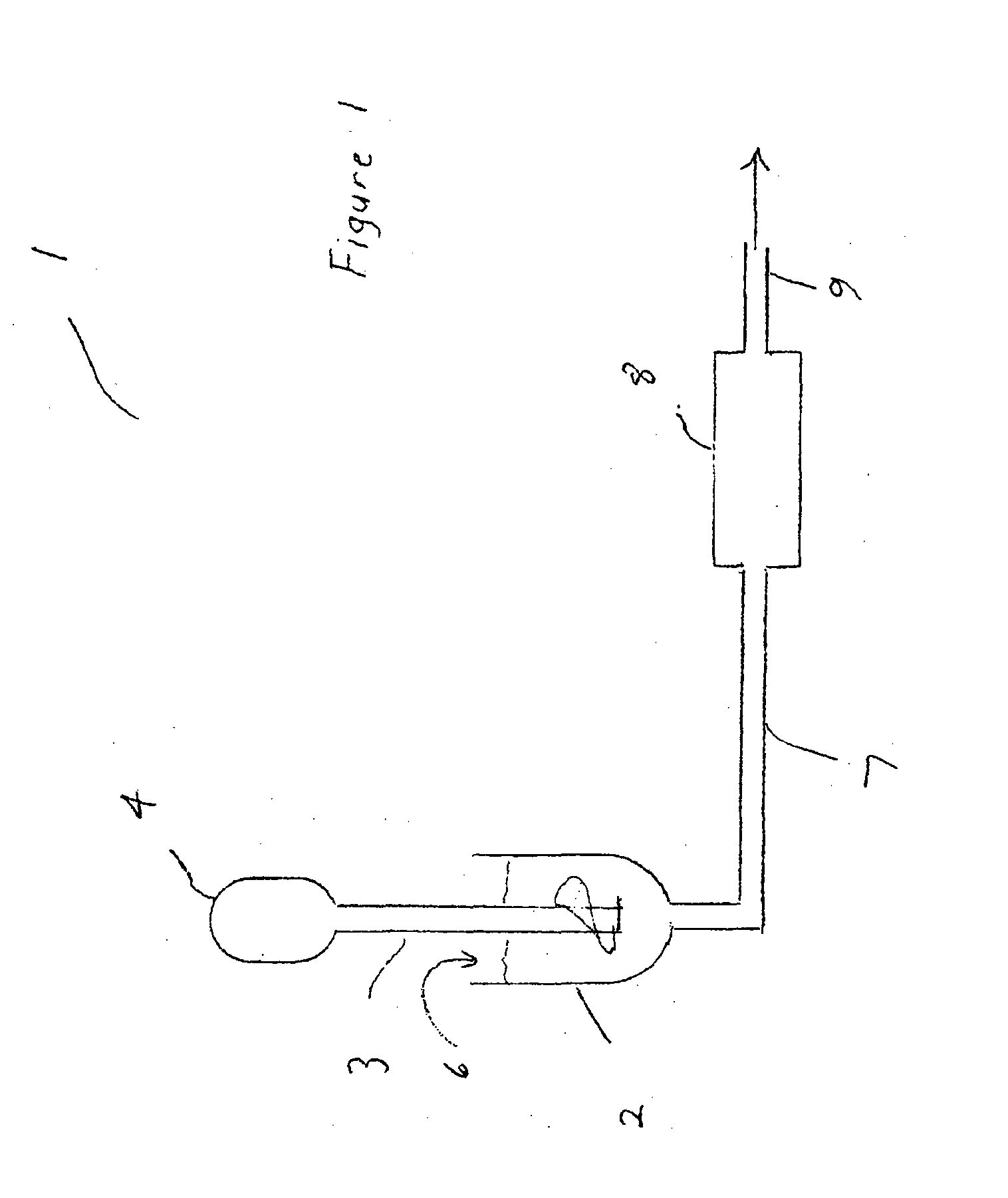
The present invention provides a system and process for measuring the magnitude of a physical variable using two measuring instruments. The first monitor changes in the physical variable and automatically calibrates the second instrument to maintain accuracy. This system and process improve the accuracy and efficiency of measuring physical variables, particularly in situations where the density of a fluid or pressure differential need to be measured.

Problems solved by technology

The invasion of petroleum products into the bore hole is such an event, and will cause a “kick” or impulse change in the characteristics of the drilling mud, causing sudden variations in, for example, the density and / or viscosity of the mud.
It is necessary to use a positive displacement pump because centrifugal pumps cannot deliver the high pressure required but positive displacement pumps can.
These assumptions may well be true when the pump is new or fitted with new parts, but may not be true when the pump is worn or in need of repair.
These pumps are high-maintenance and require frequent re-builds of the working parts.
Such wear and damage affects the accuracy of the meter.
As a practical matter, if a wedge meter is designed to work across the full range of densities of drilling mud, then it would have poor accuracy.

Method used


Image

  • Re-calibration of instruments
  • Re-calibration of instruments
  • Re-calibration of instruments

Examples


Embodiment Construction

Structure

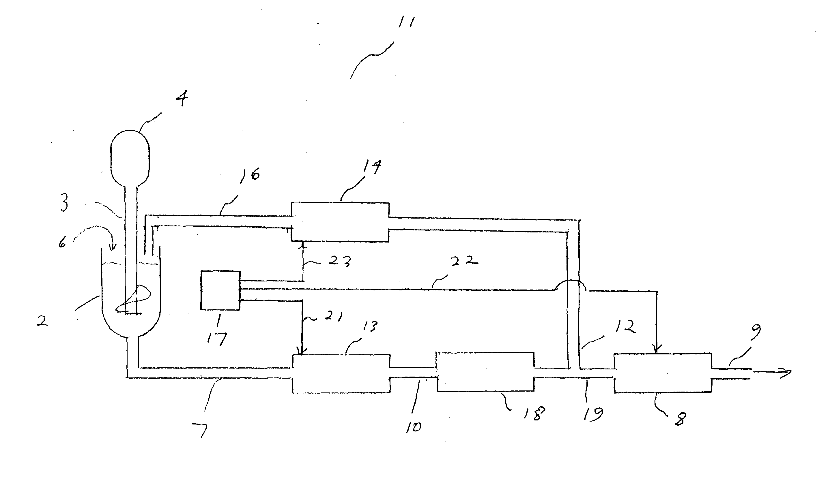
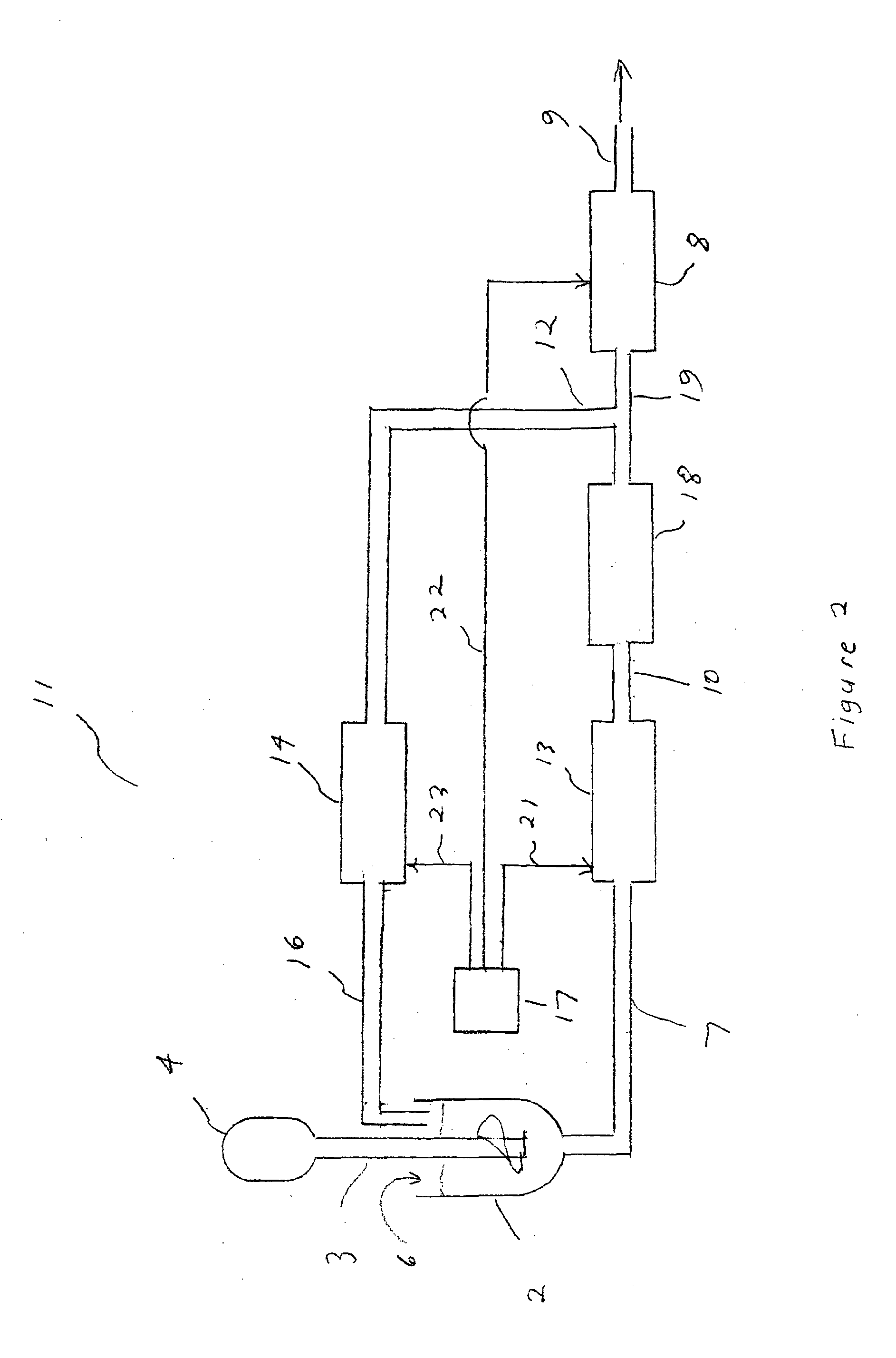
[0028]In the embodiment 11 of the invention that is illustrated in FIG. 2, a tank 2 for the supply of drilling mud 6 or the like is connected by pipe 7 to the input side of a pressure differential flow meter 13.

[0029]The output side of the pressure differential flow meter 13 is in turn connected through pipe 10 to the input of a charge pump 18. The preferred form of pump for the charge pump 18 is a centrifugal pump.

[0030]The output of the charge pump 18 is connected through a T-junction comprising pipes 19 and 12 to a positive displacement pump 8 and to a Coriolis meter 14 respectively. The preferred form of positive displacement pump is a piston pump. The Coriolis meter 14 is a type of meter that can be used to measure all of the density, the mass flow rate and the volumetric flow rate of liquid that is flowing through it. However, a Coriolis meter is not suitable for measuring the very high flows that are involved in the supply of drilling mud 6 to a drill hole.

[0031]The ...


PUM


Abstract

A pressure differential meter (13) measures and the volume flow rate of a liquid (6) and a Coriolis meter (14) monitors the density of the liquid (6). When the density as monitored by the Coriolis meter (14) indicates that density is reaching the range limit of the pressure differential meter (13), the pressure differential meter (13) is re-calibrated.

Description

FIELD OF THE INVENTION[0001]The present invention relates to the field of fluids handling, and is particularly applicable to the handling of slurries such as drilling muds. Although the present invention is described with reference to drilling muds used in the course of drilling bore holes such as oil and gas wells, it is to be understood that the invention is not limited to the field of drilling muds.BACKGROUND OF THE INVENTION[0002]Drilling muds are usually water based, but they can be based on other liquids such as synthetic oils. Additives are mixed with the liquid base. Common additives to water based drilling muds include solids such as barite, chalk (calcium carbonate) and haematite. It is required that these added solids be homogeneously mixed with the liquid base, and that the homogeneity be maintained.[0003]The physical and chemical characteristics of drilling mud also vary during the process of drilling. Depending on the geology at the depth of the drill bit, it may be ne...

Claims


Application Information

Patent Timeline
IPC IPC(8): G01F25/00
CPCG01F25/0007E21B21/08G01N9/002G01N2011/0006G01F1/36G01F1/50G01F1/88G01F25/10G01F1/34G01F1/84
Inventor SINGFIELD, CHRISTIAN ROBERT MAURICE
Owner MEZURX
Learn More