

Heat Dissipating Device
- Summary
- Abstract
- Description
- Claims
- Application Information
AI Technical Summary
Benefits of technology
Problems solved by technology
Method used
Image

Examples
Embodiment Construction
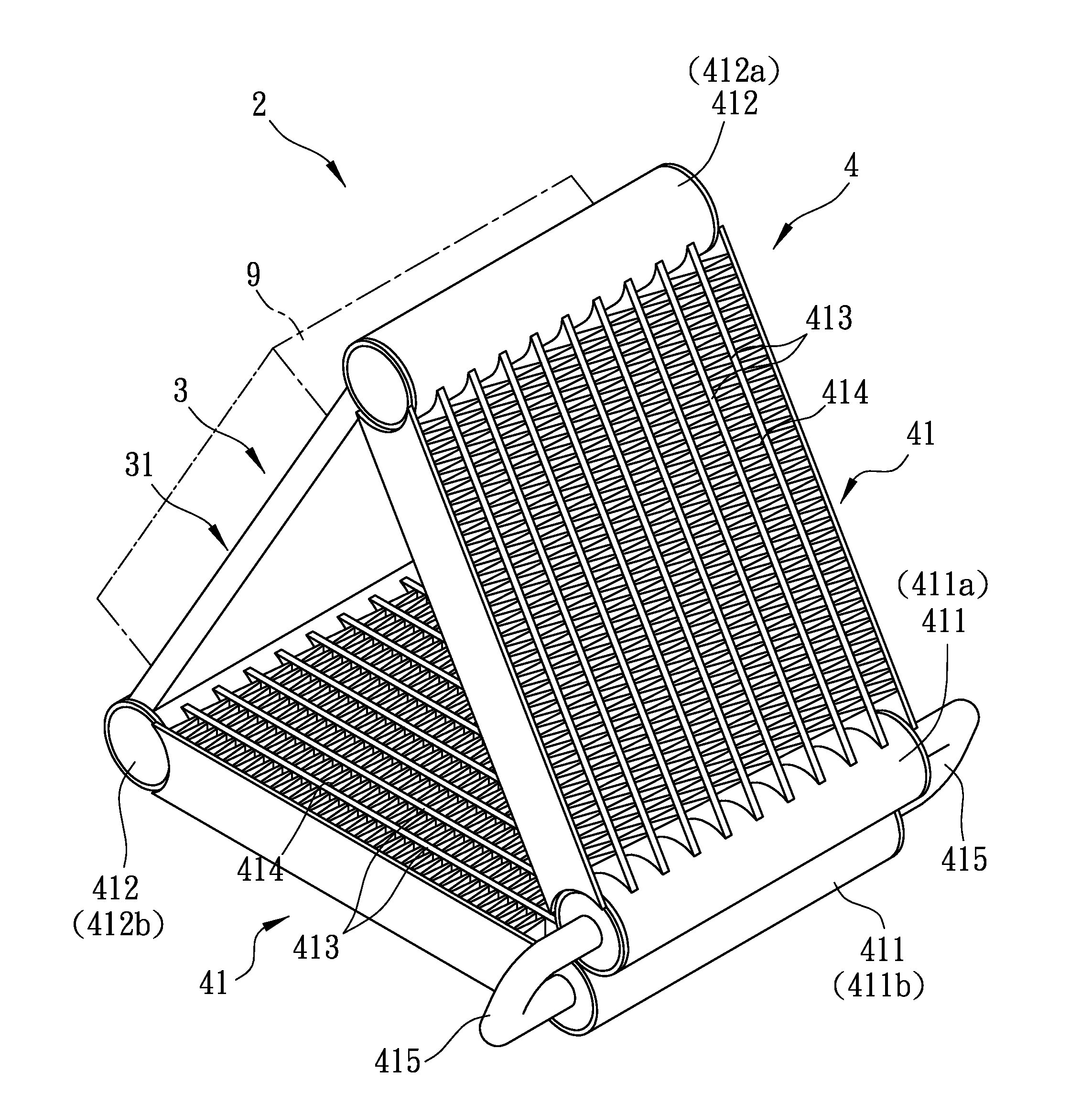
[0019]Referring to FIG. 3, a heat dissipating device 2 according to the first preferred embodiment of this invention includes a heat conducting unit 3 and a coolant storing unit 4 for storing a coolant and in fluid connection with the heat conducting unit 3. The coolant storing unit 4 includes two modules 41 in fluid connection with each other. Each module 41 includes a first coolant storage member 411, a second coolant storage member 412, a plurality of conduit members 413 fluidly connecting the first coolant storage member 411 and the second coolant storage member 412, and a plurality of heat dissipating fins 414 connected between adjacent pairs of the conduit members 413. The first coolant storage members 411 of the two modules 41 are disposed side by side with each other. A distance between the second coolant storage members 412 of the two modules 41 is greater than a distance between the first coolant storage members 411 of the two modules 41. In this preferred embodiment, the ...
PUM
 Abstract
Description
Claims
Application Information