Variable drive water line airboat

a variable geometry, airboat technology, applied in the direction of marine propulsion, rafts, vessel construction, etc., can solve the problems of fuel efficiency, torque roll, drag, overall height, propeller safety and noise,

Inactive Publication Date: 2013-11-07
MCDERMOTT ANDREW THOMAS +2
View PDF5 Cites 4 Cited by
  • Summary
  • Abstract
  • Description
  • Claims
  • Application Information

AI Technical Summary

Problems solved by technology

Many airboat operations are limited by fuel efficiency, torque roll, high center of gravity, drag, overall height, propeller safety and noise.

Method used


Image

  • Variable drive water line airboat
  • Variable drive water line airboat
  • Variable drive water line airboat

Examples


Embodiment Construction

[0016]The following detailed description is of the best currently contemplated modes of carrying out exemplary embodiments of the invention. The description is not to be taken in a limiting sense, but is made merely for the purpose of illustrating the general principles of the invention, since the scope of the invention is best defined by the appended claims.

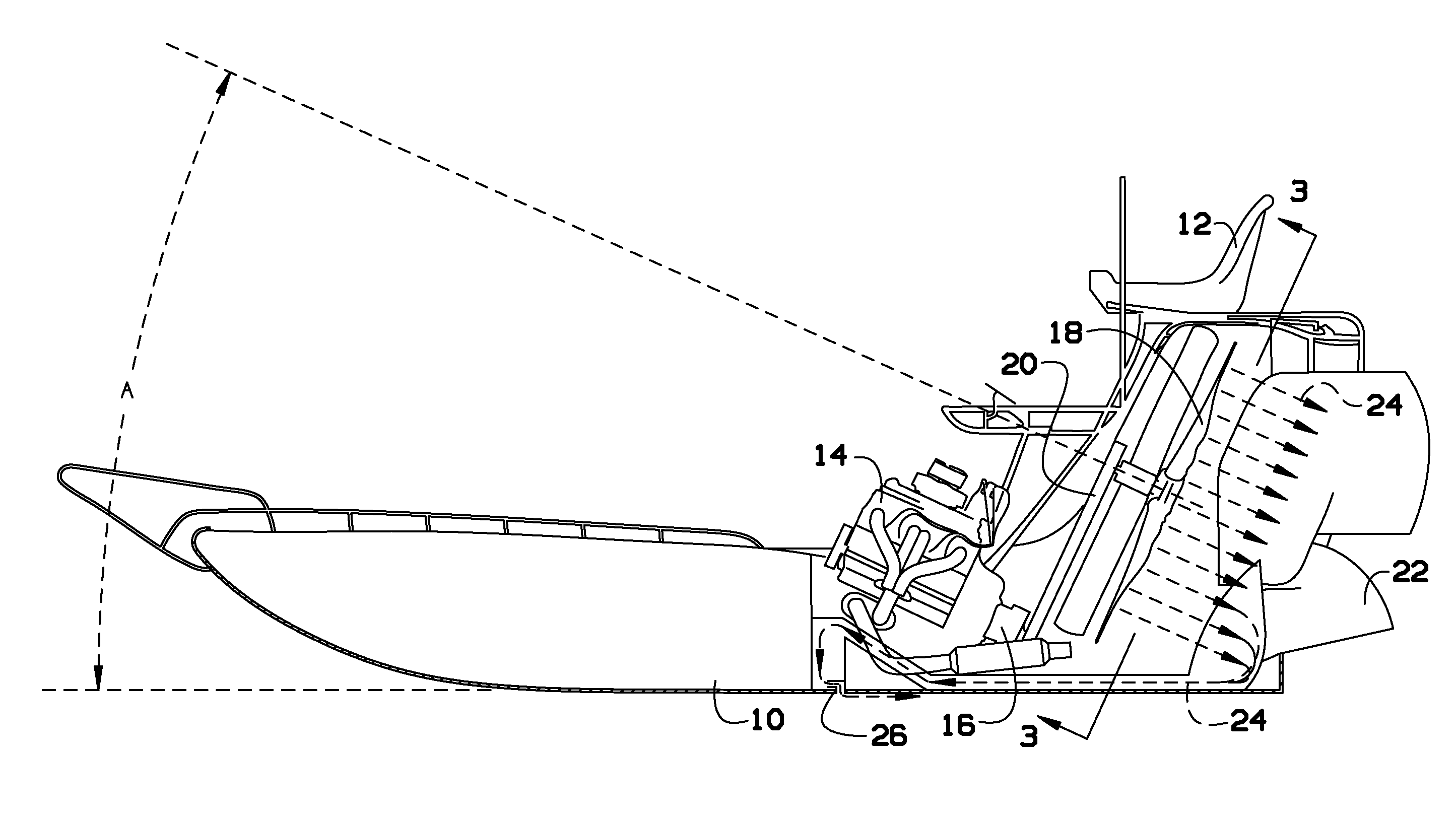
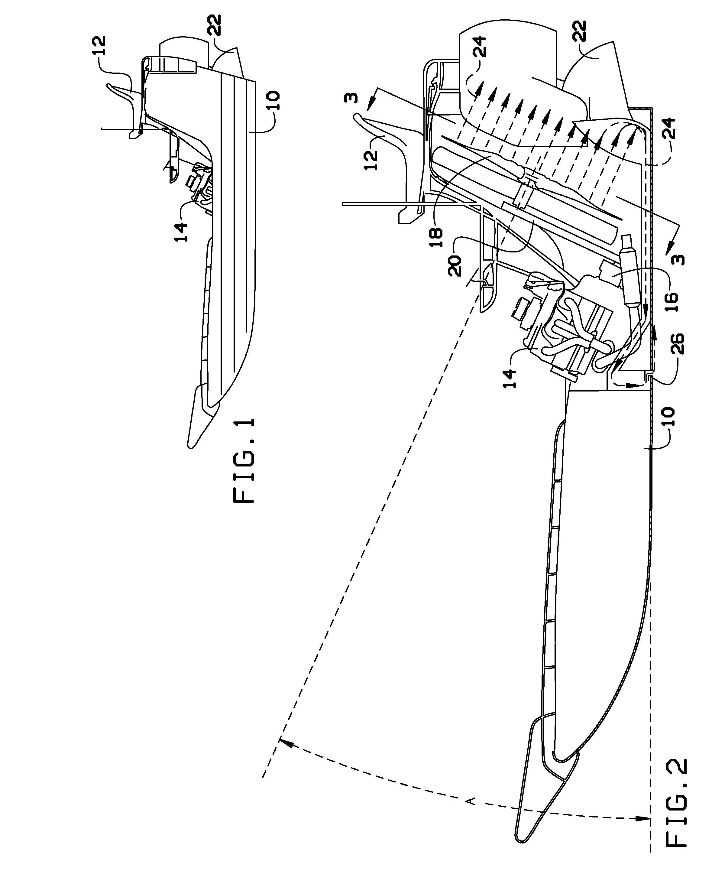
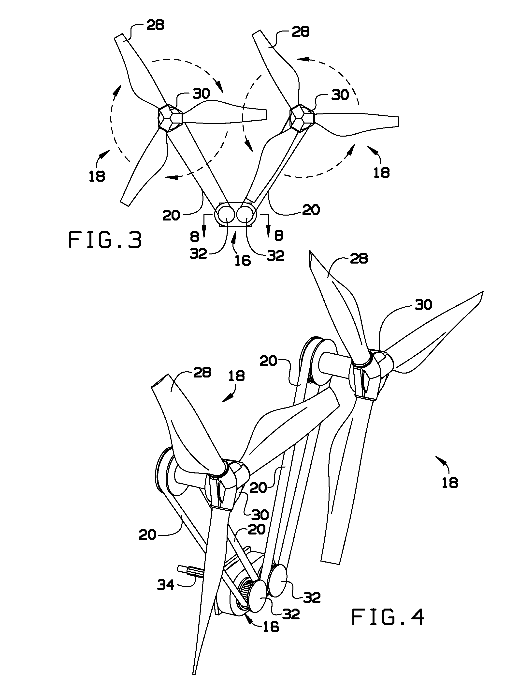
[0017]Broadly, an embodiment of the present invention provides an airboat that may include an engine that is mounted to the hull of the airboat at an angle, and at least one propeller mounted to the hull of the airboat at an angle. The canted engine and propeller design may facilitate a lower center of gravity, a lower average center of thrust above the waterline, air induction for reduced surface drag, the lowering of torque roll forces, less overall boat height, and fuel efficiency with a reduced level of noise.

[0018]The present invention may include an air propelled boat which may feature increased safety features, overall pe...


PUM


Abstract

An airboat that may include an engine that is mounted to the hull of the airboat at an angle, and at least one propeller mounted to the hull of the airboat at an angle. The canted engine and propeller design may facilitate a lower center of gravity, a lower average center of thrust above the waterline, air induction for reduced surface drag, the lowering of torque roll forces, less overall boat height, and fuel efficiency with a reduced level of noise.

Description

BACKGROUND OF THE INVENTION[0001]The present invention relates to an improved airboat and, more particularly, to an airboat with a variable geometry hull and improved drive system.[0002]An airboat, also known as a fanboat, is a flat-bottomed vessel propelled in a forward direction by an aircraft-type propeller and powered by either an aircraft or automotive engine. Airboats are a very popular means of transportation in the Florida Everglades, Frozen Arctic Tundra, Louisiana Bayous, where they are used for fishing, bow fishing, hunting and eco-tourism, and in other marshy and / or shallow / dry areas where a standard inboard or outboard engine with a submerged propeller would be impractical. Many airboat operations are limited by fuel efficiency, torque roll, high center of gravity, drag, overall height, propeller safety and noise.[0003]As can be seen, there is a need for an improved airboat.SUMMARY OF THE INVENTION[0004]In one aspect of the present invention, a airboat comprising; a hul...

Claims


Application Information

Patent Timeline
Patent Type & Authority Applications(United States)
IPC IPC(8): B63H7/02
CPCB63H7/02B63B1/18B63B35/58B63B2001/387Y02T70/10
Inventor MCDERMOTT, ANDREW THOMASWINE, DAVID EUGENEMOSSER, DAVID BRUCE
Owner MCDERMOTT ANDREW THOMAS
Why Eureka
Try Eureka