
Recirculating dryer

a dryer and circulating technology, applied in the field of recirculating dryers, can solve the problems of inefficient energy usage, inconvenient use, and insufficient heat energy utilization of traditional dryers,

Inactive Publication Date: 2013-11-14
KING FAHD UNIVERSITY OF PETROLEUM AND MINERALS
View PDF10 Cites 1 Cited by
  • Summary
  • Abstract
  • Description
  • Claims
  • Application Information

AI Technical Summary

Benefits of technology

The present invention is a recirculating dryer that includes a housing, a rotating tumbler, heated air, a flap, and a layer of moisture absorbent material. The heated air is introduced into the tumbler and recycled back to a predetermined temperature if the temperature falls below a level suitable for drying. The used air is vented at drying completion by opening the flap. The invention provides a controlled and efficient way to dry laundry while minimizing energy waste.

Problems solved by technology

This is a very effective method of drying wet clothes, but it is very inefficient in terms of energy usage.
The used hot air still contains much residual thermal energy that is continuously lost in this process.
Unfortunately, most traditional dryers have no means of utilizing or recycling heat energy.
While efficient in terms of energy consumption compared to traditional dryers, this type of dryer cannot be used on articles containing metal, such as the buttons on jeans pants and the like, for extended periods of time because of the potential arcing that can occur, which can lead to fires.
This typical condenser dryer helps reduce accumulation of excess humidity, which can have detrimental effects inside a domicile, e.g., mold.
While this type of dryer consumes less energy than traditional dryers, the laundry takes longer to dry because the recirculating air is not as dry as fresh ambient air.

Method used


Image

  • Recirculating dryer
  • Recirculating dryer
  • Recirculating dryer

Examples


Embodiment Construction

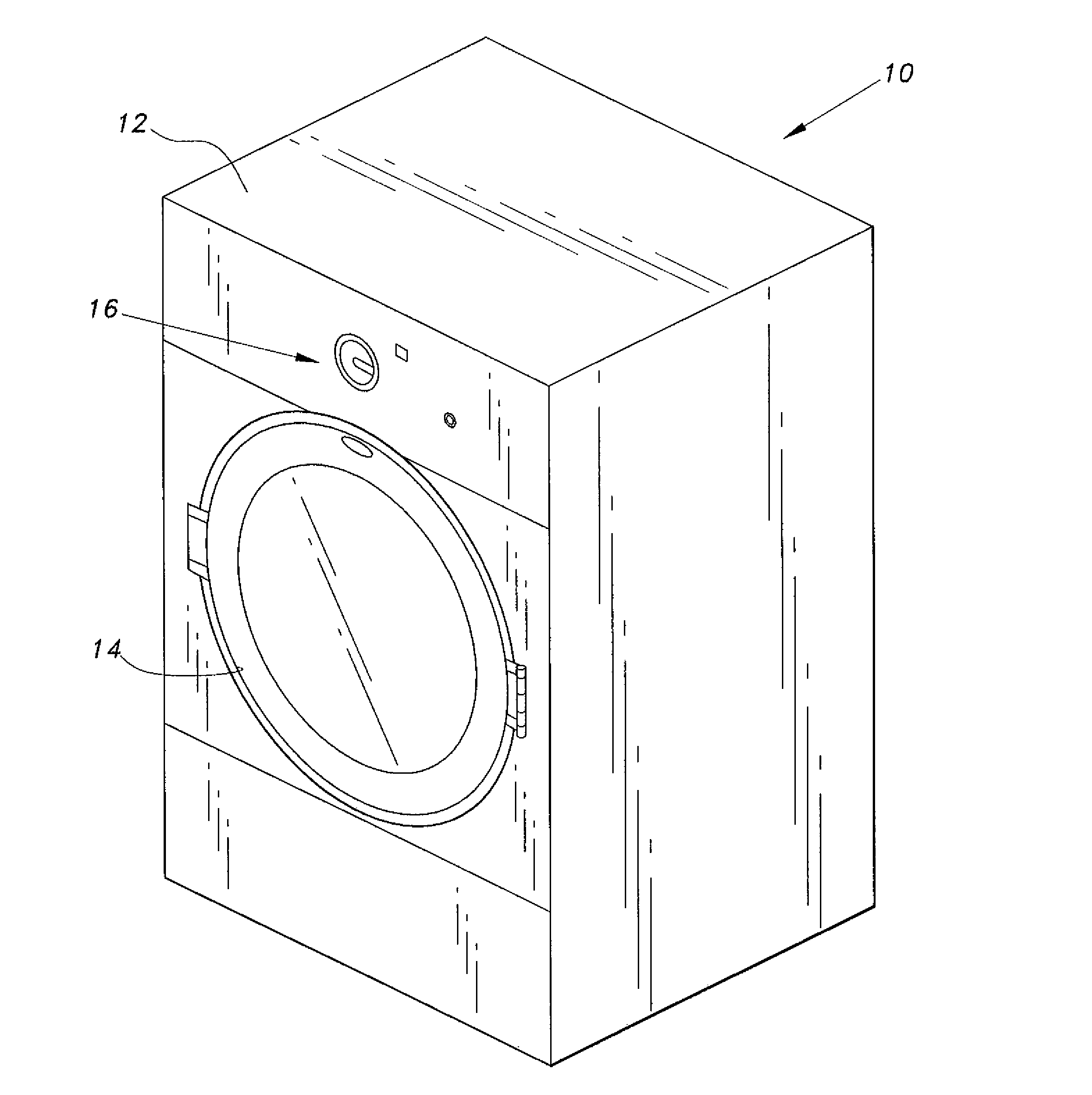
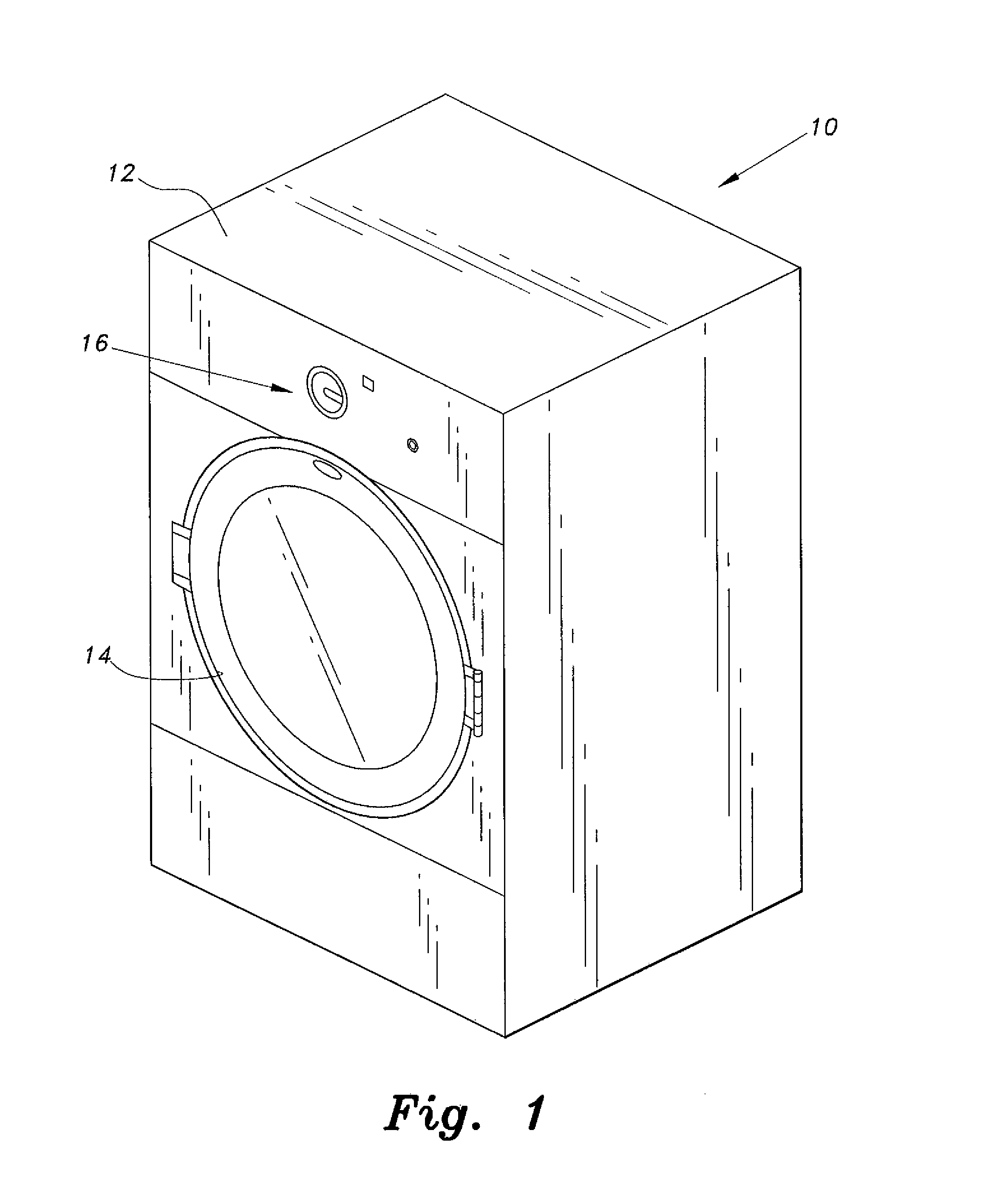
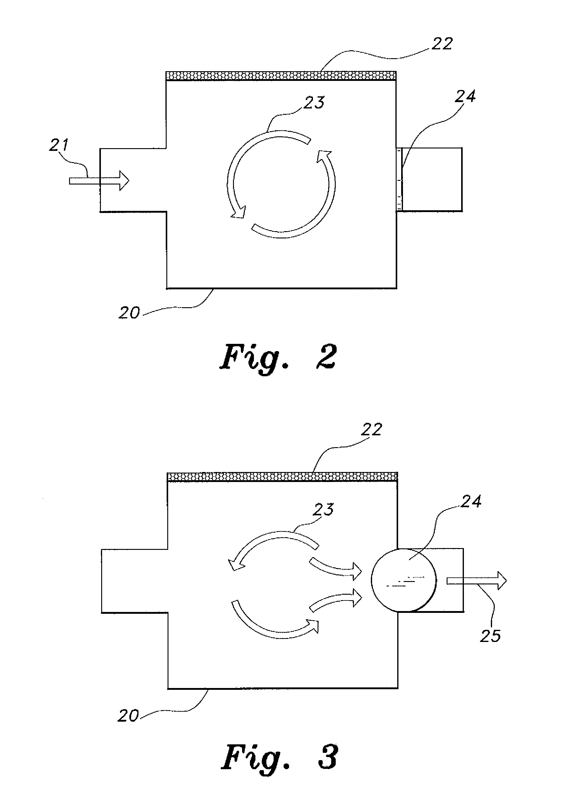
[0016]The recirculating dryer, generally referred to by the reference number 10 in the drawings, dries laundry with minimal energy consumption by actively preventing continuous energy loss from continuous venting of the used air. Instead of continuous venting, the used air is recirculated in the drying environment. This results in more efficient use of energy input, e.g., for heating, as well as more efficient use of the potential thermal energy within the used air.

[0017]As shown in FIGS. 1-3, the recirculating dryer 10 includes a housing 12 for housing the internal mechanisms of the recirculating dryer 10, a lockable cover or door 14 pivotally mounted to a side of the housing 12, and an operator control panel 16. The housing 12 is preferably box-shaped, but other shapes, such as cylindrical and variations therebetween, can also be used in construction of the housing 12. The door 14 is shown attached to the side of the housing. However, the door 14 can also be installed on top of th...


PUM


Abstract

The recirculating dryer includes a housing having an operator control panel and a locking door mounted to a side of the housing. A rotating tumbler for holding the laundry to be dried is mounted inside the housing. Heated air is introduced through an inlet of the tumbler, and the outlet is kept closed by a flap. The heated air is recirculated and recycled through the tumbler. The air is reheated back to a predetermined temperature if the temperature falls below a level suitable for drying. A layer of moisture-absorbent material surrounds the tumbler to absorb the moisture gathered in the air from the drying process. At drying completion, the flap is opened to vent the used air. A control system controls various features with data from a thermostat and a moisture detector.

Description

BACKGROUND OF THE INVENTION[0001]1. Field of the Invention[0002]The present invention relates to domestic appliances, and particularly to a recirculating dryer that provides high energy efficient drying of laundry.[0003]2. Description of the Related Art[0004]Dryers are widely used in domestic and industrial environments to dry articles of clothing and other laundry. The design of dryers has not changed much since their first introduction. Most traditional dryers continuously draw in ambient air, heat the air, and circulate the heated air through a rotating drum or tumbler containing laundry to be dried. The passage of the heated air through the laundry dries the laundry, and the used air exhausts through an outlet vent to the outside. This is a very effective method of drying wet clothes, but it is very inefficient in terms of energy usage. The used hot air still contains much residual thermal energy that is continuously lost in this process. Unfortunately, most traditional dryers h...

Claims


Application Information

Patent Timeline
IPC IPC(8): F26B21/12F26B19/00
CPCD06F58/04D06F58/24D06F58/38D06F2105/28D06F2103/36D06F2105/24D06F2103/08D06F2105/32D06F58/20D06F2103/34D06F2101/14D06F2101/18D06F2103/32D06F2101/06
Inventor DONDURUR, MEHMETSAHIN, AHMET Z.
Owner KING FAHD UNIVERSITY OF PETROLEUM AND MINERALS
Learn More